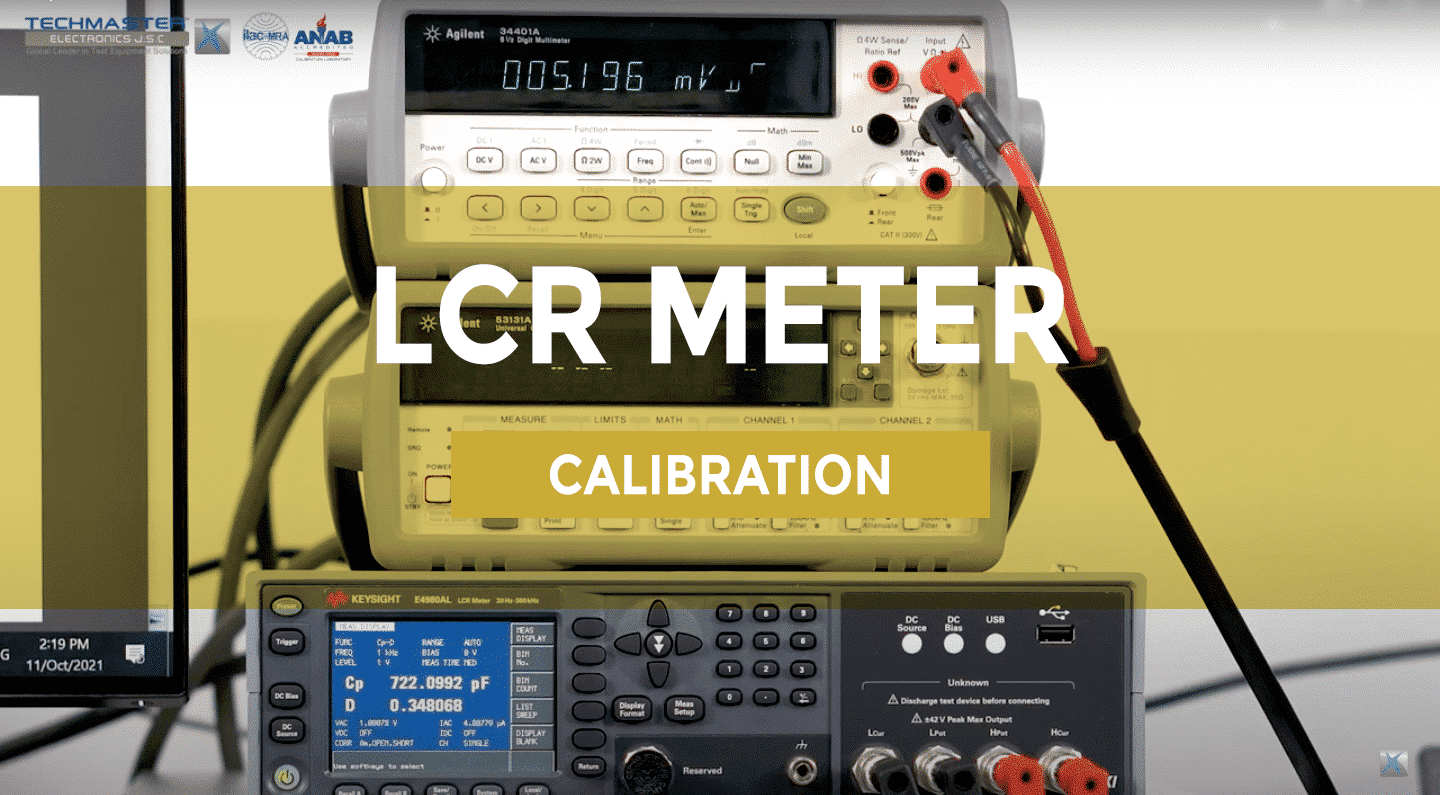
1.What is LCR Meter ?
LCR Meter is a specialized device for testing the inductance (L), capacitance (C) and resistance (R) of electronic components. This equipment is applied at laboratories, factories, warranty offices to research, develop, testand repair electronic components. The LCR Meter series possesses the ability to measure a variety of parameters: the inductor quality coefficient (Q) and the coefficient (D) is similar to Q but for resistance. With the improvement in technology, LCR Meter is integrated with other measuring devices such as oscilloscopes, pulse generators, … Provides many parameters for users to accurately assess the device status. The testing efficiency, maintenance and repair work will achieve higher efficiency.
2. Scope of procedure
| Unit Under Test Characteristics | Performance Range | Performance method |
| LCR Meter
Handhelds LCR Meter |
Up to 100 MΩ
Up to 100 μF Up to 10 H (20 Hz ~ 1 MHz) |
Comparison to by LCR Standard |
3. Standard and supporting device
✔ Digital Multimeter
✔ LCR Calibrator
✔ Standard Inductor
✔ Standard Capacitor
✔ Decade Resistor
✔ Connecting Leads/Wires
✔ LCR meter test leads / 4 BNC Connector
4. Environment conditions
Temperature: (18 ÷ 28)°C
Relative Humidity: (40 ÷ 60)%RH
5. Preparation
– Ensure UUT Fulse are of the proper value, if applicable , before beginning calibration.
– Connect UUT and test equipment to appropriate power source. Set all STANDBY / POWER ON and allow warm-up as required by the manufacturer.
– Ensure line regulation on these power supplies, vary the input voltage to the UUT by ±10%.
– Short UUT test leads together to zero. The UUT must indicate 10 counters or less.
6. Perform
6.1 Frequency Accuracy Test
– Connect UUT as show as above.
– Calibration points will be perform at 100 Hz, 120 Hz, 1kHz, 10kHz, 100kHz with 1V. Other test point follow customer’s requirements.
– Set Digital Multimeter function switch to measure frequency.
– Adjust UUT Frequency for the desired output value.
– Record the Digital Multimeter indicator.
– Repeat at least 5 times
– Repeat for remain test points.
– Disconnect test leads.
6.2 Level Accuracy Test
– Calibration points will be perform follow table below.
– Set Digital Multimeter function switch to measure VAC, VDC.
– Record the Digital Multimeter indicator.
– Repeat at least 5 times.
| Frequency | UUT Setting |
| 1kHz | 1 Vrms |
| 2 Vrms | |
| 3 Vrms | |
| 4 Vrms | |
| 5 Vrms | |
| DC | 0.5 V |
| 1 V | |
| 1.5 V | |
| 2 V | |
| 3 V |
6.3 Capacitance Calibration
– Connect UUT.
– Set UUT function measure Capacitance.
– Set UUT with signal level: 1Vrms , Trigger : Int, Speed : slow , Cable Length 1m.
| Frequency | Capacitor Value |
| 20 Hz ~ 1 MHz | 10 pF |
| 100 pF | |
| 1 nF | |
| 10 nF | |
| 100 nF | |
| 1 μF | |
| 10 μF | |
| 100 μF |
6.4 Resistance Calibration
– Connect UUT as show Fig.2 for 4 BNC connector.
– Connect UUT as show Fig.3 for LCR meter test leads.
– Set UUT function measure Resistance.
– Set UUT with signal level: 1Vrms , Trigger : Int, Speed : slow .
– Set UUT range dependent on the appropriate resistance in table below. Other test point follow customer’srequirements.
| Frequency | Resistor Value |
| 20 Hz ~ 1 MHz | 0.1 mΩ |
| 1 mΩ | |
| 10 mΩ | |
| 100 mΩ | |
| 1 Ω | |
| 10 Ω | |
| 100 Ω | |
| 1 kΩ | |
| 10 kΩ | |
| 100 kΩ | |
| 1 MΩ | |
| 10 MΩ | |
| 100 MΩ |
– Repeat at least 5 times.
– Repeat the above steps with other frequency points.
– Disconnect the resistance from UUT test leads.
6.5 Inductance Calibration
– Connect UUT as show Fig.2 for 4 BNC connector.
– Connect UUT as show Fig.4 for LCR meter test leads.
– Set UUT function measure Inductance.
– Set UUT with signal level: 1Vrms , Trigger : Int, Speed : slow .
– Set UUT range dependent on the appropriate inductor in table below. Other test point follow customer’s requirements.
| Frequency | Inductor Value |
| 20 Hz ~ 1 MHz | 10 μH |
| 100 μH | |
| 1 mH | |
| 10 mH | |
| 100 mH | |
| 1 H | |
| 10 H |
– Record the UUT value.
– Repeat at least 5 times.
– Repeat the above steps with other frequency points.
– Disconnect the inductancefrom UUT test leads.
Calibration now completed, turn off, disconnect and secure all equipment.
*Note : Other function of equipment reference to the manufacturer’s instructions or customer’s requirement.
7. Tolerance
– Customer required tolerances are to be used for all calibrations unless otherwise noted.
– If the customer does not supply instrument tolerances then manufacturing specifications or other approved sources are to be used as the default tolerance.
– If not, non-judgement results will be applied