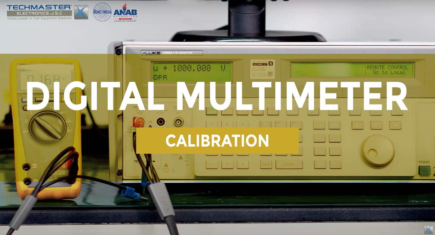
Digital Multimeter is the electrical industry familiar device , all electrical technicians need this device. Digital Multimeter Calibration ensures correct operation instrument, currently many businesses are interesting.
1. Introduce Digital Multimeter
Digital Multimeter can also be applied in automatic measurement systems in the production of components and sell end-product in the electronics and auto industries…After fully programmed, the device will measure and send the measured parameters to the production system for real-time product quality control.
2. Digital Multimeter classification
Digital Multimeters are classified based on indication structure, convenience or accuracy.
2.1. Analog Multimeter

This type performs measurements such as voltage, resistance, Volt-Ohm-Milliam-Meter (VOM). Measurement results based on indicator needle. Low cost but not high accuracy, is gradually being replaced by electronic type.
2.2. Digital Multimeter – DMM
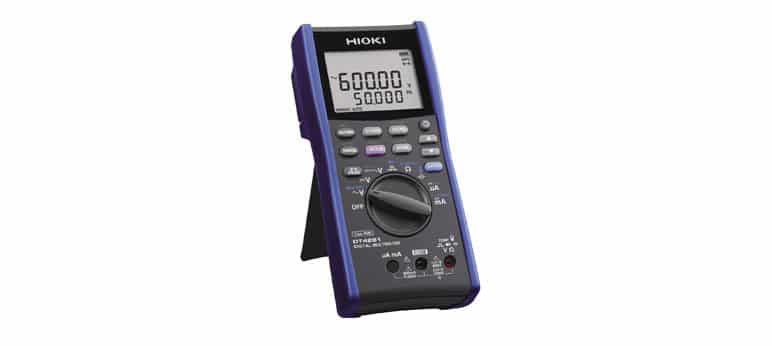
This type has measurement results displayed on a liquid crystal display. Compared with Analog, this type integrates more functions and wider scale, higher accuracy, and has more standards of anti-shock for the device. The price is higher. The device is compact but can check many parameters, so many electrical technicians are trusted. Currently, the digital multimeters calibration is also of interest to many businesses.
2.3. Pocket multimeter
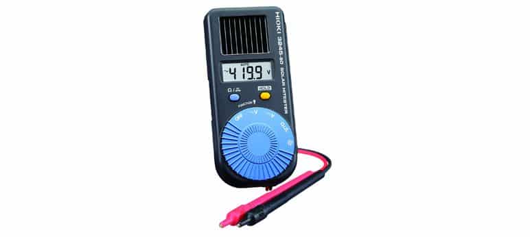
This type has a compact design, pocketable, very convenient to carry, no power required. This type has higher accuracy than Analog type but lower than Digital type.
2.4. Precision Multimeter
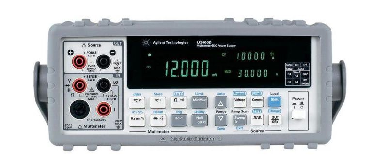
Precision Mutimeter (Bench Multimeter) is a specialized type for measurement and calibration laboratories. High accuracy, for results up to 6 ½ digit. This instrument is applicable to complex measurement requirements.
3. Scope of procedure
| Unit Under Test Characteristics | Performance Range | Performance method |
|
DC Voltage |
Up to 1.1 kV |
Direct measurement to by a known DC Voltage |
|
DC Current |
Up to 20A |
Direct measurement to by a known DC Current |
|
AC Voltage |
Up to 22 V 10 Hz to 1 MHz 22 V to 220 V 10 Hz to 300kHz 220 V to 1.1 kV 15 Hz to 1kHz |
Direct measurement to by a known AC Voltage |
|
AC Current |
Up to 3 A |
Direct measurement to by a known DC Current |
|
Resistance |
Up to 330 MΩ |
Direct measurement to by a known Resistance |
|
Capacitance |
Up to 110 mF |
Direct measurement to by a known Capacitance |
|
Frequency |
10 Hz to 1.1 MHz |
Compared to a Calibrator with known Frequency Response |
|
Diode |
Up to 10 V |
Compared to a known DC Voltage |
|
Temperature |
Type K (-200 to 1372) ºC |
Calibrator generates a signal for thermocouple simulation calibration. |
4. Standard and supporting device
✔ Calibrator, accuracy better than 3 times Unit Under Test (UUT).
5. Environment conditions
– Temperature: (18 ÷ 28)°C
– Relative Humidity: (40 ÷ 60)%RH
6. Preparation
– Technician must be familiar with calibration techniques and the operator manual of the UUT being calibrated.
– Connect TI and test equipment to appropriate power source. POWER ON and allow warm-up as required by the manufacturer.
7. Perform
7.1 DC Volts calibration
– Connect UUT DC VOLTS terminals to Calibrator OUTPUT terminals, observing polarity.
– UUT setting switch to DC Voltage mode. Some UUT require the test leads be changed to different jacks for range changes.
– On the Calibrator set the desired output value, then press OPR/STBY switch to OPR and read UUT value when it is stable.
– Set Calibrator OPR/STBY switch to STBY.
– Repeat the above process to test each DC Voltage range of UUT.
– Disconnect UUT from Calibrator.
7.2 DC Current Calibration
– Connect UUT DC Current terminals to Calibrator OUTPUT terminals, observing polarity.
For current >3 A, must change the test lead to the 20A terminal on the Calibrator.
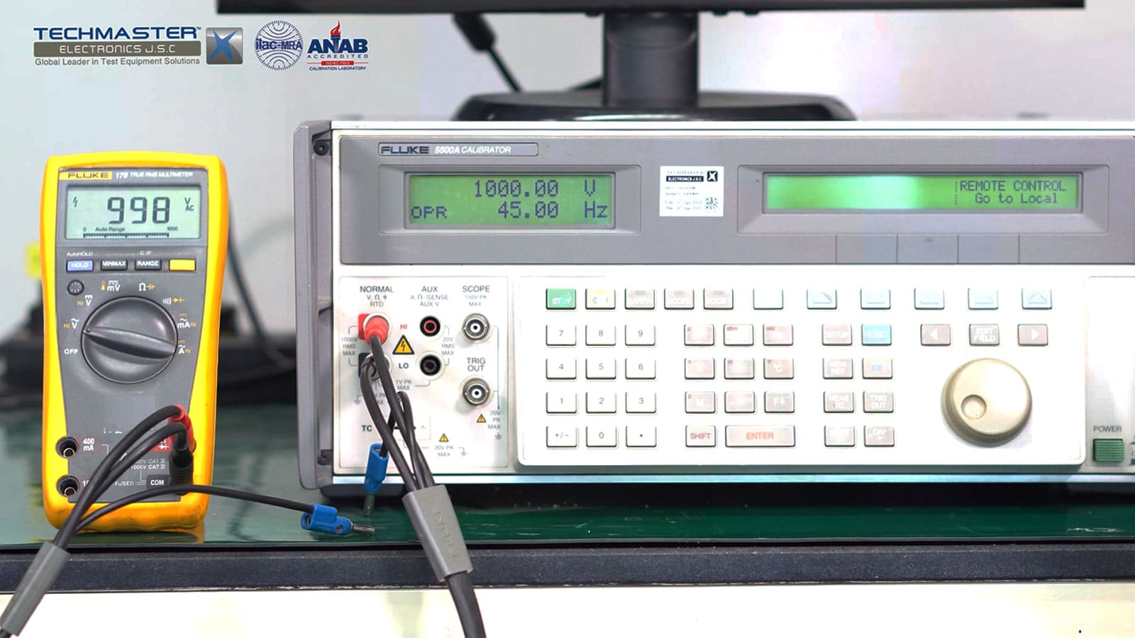
7.3 AC Volts Calibration
– For calibration of AC Volts function, calibration points will be perform at approximately 10%, 30%, 50% and 95% of UUT range. Other test point from 0 to 100% UUT range can be done follow customer’s requirements.
– Connect UUT AC VOLTS terminals to Calibrator OUTPUT terminals.
– UUT setting switch to AC Voltage mode. Some UUT require the test leads be changed to different jacks for range changes.
7.4 AC Current Calibration
For current >3 A, must change the test lead to the 20A terminal on the Calibrator.
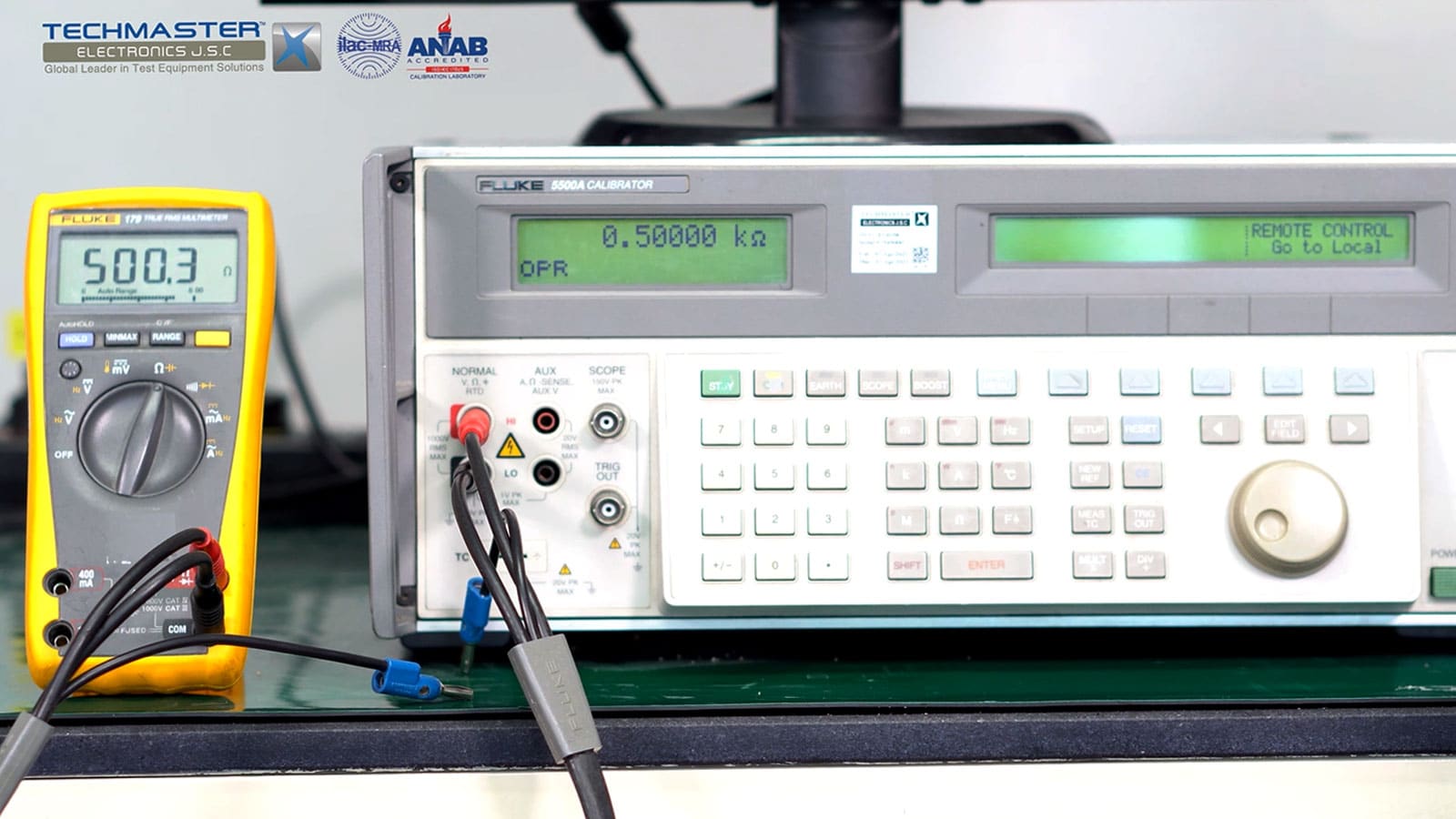
7.5 Resistance Calibration
– Connect UUT OHMS terminals to Calibrator OUTPUT terminals.
7.6 Capacitance Calibration
– Connect UUT terminals to Calibrator OUTPUT terminals, observing polarity.
– UUT setting switch to Capacitance mode.
– Set Calibrator OPR/STBY switch to STBY.
– Repeat the above process to test each Capacitance range of UUT.
– Disconnect UUT from Calibrator.
7.7 Frequency Calibration
– For calibration of Frequency function, calibration points will be perform at approximately min, 50% and max of UUT range. Other test point from min to max UUT range can be done follow customer’s requirements.
– Connect UUT AC VOLTS terminals to Calibrator OUTPUT terminals.
– UUT setting switch to ACV and choose Frequency Mode.
– On the Calibrator set the desired output value at 3V, then press OPR/STBY switch to OPR and read the value when it is stable.
– Set Calibrator OPR/STBY switch to STBY.
– Repeat the above process to test each point frequency of UUT.
– Disconnect UUT from Calibrator.
7.8 Diode Calibration
– For calibration of Diode function, calibration point will be perform at approximately 75% of UUT range.
– Connect UUT DC VOLTS terminals to Calibrator OUTPUT terminals, observing polarity.
– UUT setting switch to Diode mode.
– On the Calibrator set the desired output value, then press OPR/STBY switch to OPR and read the value when it is stable.
– Set Calibrator OPR/STBY switch to STBY.
– Disconnect UUT from Calibrator.
7.9 Temperature Calibration
– Connect UUT DC VOLTS terminals to Calibrator OUTPUT terminals, observing polarity.
– UUT setting switch to Temperature mode.
– On the Calibrator select the thermocouple type K and enter the desired output value, then press OPR/STBY switch to OPR and read the value when it is stable.
– Set Calibrator OPR/STBY switch to STBY.
– Disconnect UUT from the Calibrator and secure all equipment
8. Tolerance
– Customer required tolerances are to be used for all calibrations unless otherwise noted.
– If the customer does not supply instrument tolerance then manufacturing specifications or other approved sources are to be used as the default tolerance.