Particle Counter Tubing & Particle Transportation
Transportation of particles through particle counter tubing between the sample inlet and the optics of the instrument has often been at the forefront of discussion regarding the truth of readings. The experts at Particle Measuring Systems (PMS) deal with this regularly and across a wide range of applications.
With the release of the 2009 EU GMP Annex 1 the issue of particle loss of large particles was elevated such that a better understanding and measurement of those losses is warranted. When the validation implications of losses due to various forces are reviewed, the absolute certainty of a result is always in question. So what are these forces? What are the losses? What are acceptable results? This paper on particle counter tubing addresses several of these issues and provide a better understanding of the problem.
Read this paper to better understand particle counter tubing and:
- Forces Acting on Particles
Cleanroom certification and monitoring activities can be seen as those tests performed to quantify the dynamics of the body of air within a confined space. This space may be either the air in the general cleanroom or the air in a transport duct or a laminar flow zone. Learn about particle behavior mechanisms and the understanding of sampling difficulties and how to improve the efficiency of particle counter sampling - Isokinetic Sampling
There are several ways in which one can design a particle counter tubing system to minimize these forces and their impact on sampling errors. In laminar flow environments, or in ducts leading to a filter, the air is considered to be moving unidirectionally. The sampling of this air flow must neither over-sample nor under-sample the distribution of particles within that flow. This requirement is satisfied when isokinetic sampling is performed. Isokinetic sampling means that the air velocity in the supply air is the same as the air velocity in the particle counter tubing inlet - Particle Loss in Transport Tubing
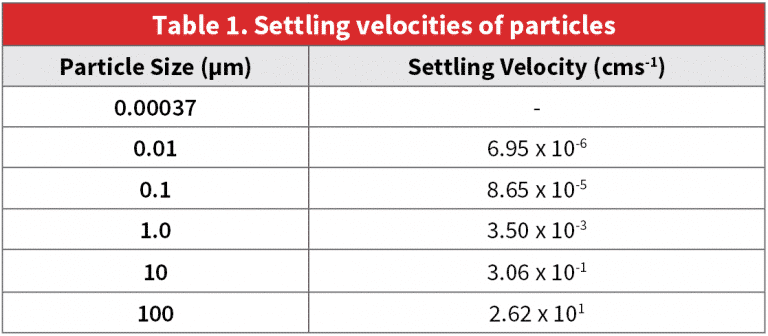
When a sample is taken for either cleanroom certification/qualification or routine monitoring operations, it is not uncommon for the isokinetic sample probe (ISP) to be in a remote location from the particle counter optics, requiring that the sample be drawn through tubing to the particle counter. When the sample is to be transported any significant distance in the tube from the point of sampling to the point of measurement, some particle losses will occur in the transport tubing. Such losses are dependent on tubing type, flow velocity, particle diameter, and distance. When directional changes occur, large particles are lost by a combination of gravitational settling to the bottom of the duct or tubing and inertial deposition on the walls of the tubing. Small particles are lost to the duct or tubing walls by Brownian motion and diffusion effects. - Practical Considerations and Guidance
Defining acceptable losses for particle transport is difficult, as any loss can be deemed to be unacceptable. However the practical implications of installing sensors on production equipment can be considered, along with the uncertainties and tolerances for particle counters. The ideal installation of particle sensors would eliminate tubing to avoid losses altogether. But this is not often a practical choice given that sampling locations are often inside production equipment with limited space where a sensor cannot be installed. When the installation of transport tubing is required, questions arise as to what length of tubing is acceptable and how best to install it.