Introduction Dial – Digital – Dial Test Indicator and Dial – Digital – Dial Test Indicator Calibration.
1. Introduction Dial – Digital – Dial Test Indicator
Dial – Digital – Dial Test Indicator is a familiar device in the field of mechanical processing or construction. This device is used to check the height, thickness, and inversion of the parts. Flexible application when combined with other devices such as height ruler, stone table, magnetic base, centering device,…
2. Dial – Digital – Dial Test Indicator Classification
- Dial Indicator Standard Type: The measuring head and measuring axis can be moved up or down, measuring line from 0.002mm to 0.01mm and measuring range from 0 – 1mm or 0 – 5mm or 0 – 10mm.
- Dial Indicator (lever): Apply the principle of lever to amplify the movement of measuring head, the measuring head is small and the measuring angle can be changed freely. This meter has a small measuring range, usually less than 1mm, but the resolution is better: 1µm, 2µm, 5µm.
- Large Dial Indicator (long type): The dial indicator is similar to the standard type, but has a larger measuring range. Measuring range from 20mm – 100mm and graduated from 0.01mm or more.
2.1. Standard Type
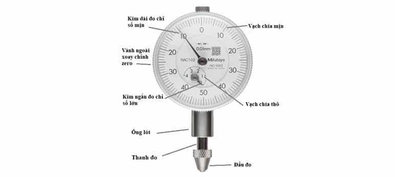
Structure and operation: Dial Indicator is a device with a structure consisting of: dial, set screw, rim, handle, ring indicator hands, measuring rod, measuring head, measuring rod guide bush and a number other parts. The long hand has a fine index, the short hand has a rough index. As the probe moves, the gear mechanism amplifies the reading on the dial.
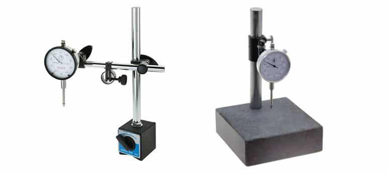
Usage: the device is mounted on a stone table or base from the folding legs in the bushing. The measuring head is in contact with the measuring face (standard face), turn the dial to “0” to set the zero point. Lift the hand up a notch and feed the part above the reference face. Gently let the probe touch the part to be measured. Read the dial readings from the long and short hands. The standard surface here can be the stone table top, the face of the sample room or the position on the part to be compared.
For example with the clock in the picture above: the long hand rotates more than 2 turns and to 10, the short hand rotates one round past the number 1. The calculation of the result is: 1mm + 10*0.01mm = 1.10mm. Here one division corresponds to 0.01mm.
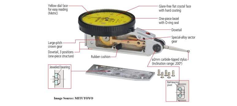
2.2. Dial Indicator Type

Structure and operation: Dial Indicator Type based on the lever principle, including a measuring head and a gear mechanism that magnifies the movement of the measuring head into a reading on the dial. This type has a shank that attaches to attachments such as a folding base, a stone table or a tall ruler.
Usage: the device is mounted on the base from the folding legs or the height gauge at the shank. The measuring head is in contact with the part to be compared. The angle of the measuring needle with the direction of the reference plane should not exceed 5o. Rotate the dial to zero to set the zero point. Rotate the part on the rotating platform, or level it with a level gauge, to determine the maximum difference in run-out or flatness.
For large angles θ, it is necessary to multiply the compensation factor for the measured result. For example the measurement result is 0.200mm, the actual result is:
_ With angle θ = 10o, complement coefficient is 0.98, result = 0.200*0.98 = 0.196mm
_ With angle θ = 20o, complement coefficient is 0.94, result = 0.200*0.94 = 0.188mm
_ With angle θ = 30o, complement coefficient is 0.86, result = 0.200*0.86 = 0.172mm
Note: the above coefficients are referenced from MITUTOYO company.
3. Measurement methods
Comparative measurement method: Place the probe in contact with the position to be compared on the product detail. Rotate the watch face to “0”. Then insert the next measuring position to determine the deviation between the two positions. The comparative measurement method reduces errors caused by measurement conditions such as temperature errors, measuring force errors, assembly errors, manufacturing errors and subjective errors due to the observer.
Absolute measurement method: Place the probe in contact with the table. Adjust the meter to read 0 then put the detail into the measurement. The watch number will be the absolute size of the part.
4. Why should we calibrate Dial – Digital – Dial Test Indicator?
The Dial Indicator is widely used in industries, in the detailed measurement of products. The device is used almost continuously and always requires high accuracy to provide reliable measurement results. Periodic calibration will ensure that the meter works correctly, ensure the quality of work, and monitor product quality.
5. Dial – Digital – Dial Test Indicator Calibration
5.1. Standard and supporting device
- Gauge Block Set grade 0, 1 or 2, better than 4 times accuracy of Unit Under Test (UUT).
- Dial indicator calibrator: MITUTOYO UDT-2, UDT-3
- Dimensional Length Measuring System (DMS)
- Indicator Stand
- Alcohol, lint-free cloth, gloves.
5.2. Environment conditions
- Temperature: (19 ± 2)ºC
- Relative Humidity: (20 ÷ 65)%RH
Note: environment conditions above apply for Techmaster inhouse laboratories. Outside this bound conditions will be considered with customer for uncertainty and measurement results.
5.1. Preparation
- Visually inspect the UUT for obvious damage that may affect accuracy and/or operation and note any observations.
- Clean the contact rods; check moving smoothly.
- Clean surface plate in the area of calibration, clean all gauge blocks, MITUTOYO UDT-2, UDT-3, measuring rods of DMS use for calibration.
- All UUT and Standard must cold to proper temperature conditions at least 1 hour before calibrated.
- UUT should be clamped on the surface plate with stand, indicator stand, or clamped on the clamp base of the DMS, UDT-2, UDT-3.
- Technician must be familiar with calibration techniques and the operator manual of the UUT being calibrated.
- Connect the UUT to an appropriate power source, if applicable
5.4. Perform
5.4.1. 1 Direction calibration method
5.4.1.1 Using Gauge Block Set and Surface plate
- Set up the test equipment as shown in Figure below.
- Ensure the UUT plunger is perpendicular to the Serrated Anvil on the Surface Plate to eliminate cosine error.Preload the UUT plunger against the Serrated Anvil about 0.25mm or 0.010 inch.
- Set zero on UUT by zero button, or rotate dial scale on the indicator to 0.
- Select single Gage Blocks equal to about 25%, 50%, 75% and 100% of UUT full scale.
- Other test point can be done follow customer’s requirement.
- Set the UUT to the correct range and resolution.
- Place the Gage Block equal to about 25% of UUT full scale under the UUT probe tip using the lifting lever toraise the probe (if applicable), record value.
- Repeat measure steps above for each remaining Gage Block size.
5.4.1.2 Using Mitutoyo UDT-2, UDT-3
- Set zero on MITUTOYO UDT-2, UDT-3 dial scale.
- Clamp UUT on UDT, plunger of UUT is perpendicular to Anvil Surface of UDT-2. For dial test indicator (folding leg), probe tip of UUT is close to horizontal with Anvil surface of UDT-3 to eliminate cosine error.
- Preload the UUT probe tip against the UDT Anvil about 5~10 divisions.
- Set zero on UUT.
- Rotate dial scale UDT upward to create test points about 25%, 50%, 75% and 100% of UUT full scale, record values.
5.4.1.3 Using DMS
- Clamp UUT on clamp base of DMS
- Plunger of UUT is perpendicular to Anvil Surface of DMS to eliminate cosine error.
- Preload the UUT probe tip against the DMS Anvil about 5~10 divisions.
- Set zero on UUT and DMS.
- Using fine moving function of DMS, to the right direction, create test points about 25%, 50%, 75% and 100% of UUT full scale, record values.
5.4.2. 2 Direction calibration method
This method apply for dial test indicator, pic-test indicator, which has reading 0-X-0 or X-0-X (X: number of devisions of reading scale range).
5.4.2.1. Using UDT-2, UDT-3
- Set zero on MITUTOYO UDT-2, UDT-3 dial scale.
- Clamp UUT on UDT, plunger of UUT is perpendicular to Anvil Surface of UDT-2. For dial test indicator (folding leg), probe tip of UUT is close to horizontal with Anvil surface of UDT-3 to eliminate cosine error.
- For UUT has reading scale type 0-X-0, preload UUT probe tip against the UDT Anvil at X number, for UUT has reading scale type X-0-X, preload at 0. This is center scale indicating of UUT.
- For digital, electronic type of indicator, preload and set zero at this center scale indicating also.
- Perform test for 2 directions: Positive direction (Clock Wise) and Negative direction (Counter-Clock Wise). Each direction will be done as below test points.
- Rotate dial scale UDT upward to create test points about first 10 divisions, 50%, 75% and 100% of UUT left / right scale, record values.
- Example for UUT 0-40-0 division, 1div. = 0.01mm, test points for left / right scale is 10,20,30,40 divisions.
5.4.2.2. Using DMS
- Clamp UUT of DMS base same as 5.1.3.
- Set zero on UUT and DMS same as 5.2.1
- Perform test for 2 directions, all test points are the same as 5.2.1.
Dial – Digital – Dial Test Indicator Calibration

Dial Indicator Standard Type Calibration
5.4.3. Thickness gauge indicator
- Release trigger clamp on UUT, 2 anvil of UUT are fully contact.
- Set zero on UUT
- Using gauge block size close to 25%, 50%, 75% and 100% of UUT measuring range.
- Using UUT measure blocks above, record values.
6. Tolerance
- Customer required tolerances are to be used for all calibrations unless otherwise noted.
- If the customer does not supply instrument tolerances then manufacturing specifications or other approved sources are to be used as the default tolerance.
- If not, non-judgement results will be applied.