Profile Projector Calibration at Techmaster
Profile projector, also known by other names such as image projector, optical profile projector,… This measuring device is widely used in laboratories, research centers even in industries such as machine building, electronics, aviation, etc.
Therefore, it is extremely important to ensure this equipment operates stably and correctly. The Profile Projector therefore needs to be calibrated periodically. Join us to learn about the Profile Projector Calibration Process at Techmaster.
1. What is Profile Projector?
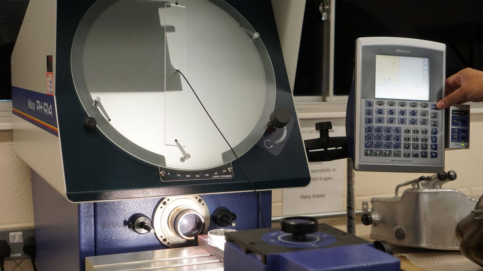
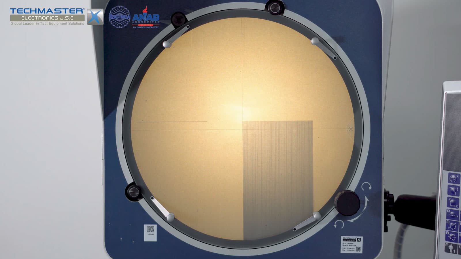
Profile Projector works based on optical principles. The shadow of the object to be measured will be projected onto the projection screen thanks to the light source from the projector, combined with a system of condensers, lenses and mirrors. The shape of the object will be enlarged on the projection screen. The user will then use the tools on the machine to measure the size of the object.
2. Profile Projector Advantages
3. Profile Projector Applications
Profile Projector is an indispensable measuring device in industrial production fields such as machine building, electronic component manufacturing, plastic, etc. This equipment will help to check and evaluate product quality during production. Laboratories and research institutes also use this equipment to test and evaluate product quality as well as to research new products.
4. Profile Projector Calibration Process
4.1 Why should we calibrate Profile Projector ?
This is an important measuring device to ensure the quality of the production process. This calibration helps to assess the operating status of Profile Projector. Therefore, the calibration of this device is extremely necessary. This work helps to ensure stability and accuracy for related activities. Calibration will help detect equipment failures (if any) in time for timely correction and repair.
4.2 Equipment, standard requirements
- Standard glass scale set range up to 500mm.
- Gauge block set range up to 25mm.
- Cleaning material: Alcohol, lint-free cloth, gloves.
4.3 Environment conditions
- Temperature: (19 ± 2)ºC
- Relative Humidity: (20 ÷ 65)%RH
Note: environment conditions above apply for Techmaster inhouse laboratories. Outside this bound conditions will be considered with customer for uncertainty and measurement results.
4.4 Preparation
- Clean UUT travel table and screen, ensure UUT is free from any obvious defects that would impair its use:
_ The travel table of X and Y-axis of machine shall move gently.
_ The adjuster of lens and focal length of profile projector must be in good operations
_ The screen of machine must glow steadily, the image on the screen must clear.
_ For digital the profile projector: all indicators must be seen clearly.
- Place standard glass scale, gauge block set near UUT, allow them stabilize at least 1 hour.
- Turn on machine / equipment at least 30 minutes for warm-up, measurement software start up.
- Technician must be familiar with calibration techniques and the operator manual of the UUT being calibrated.
4.5 Perform
4.5.1. X, Y-axis calibration
- Select suitable standard glass scale size equal or larger than UUT measuring capacity
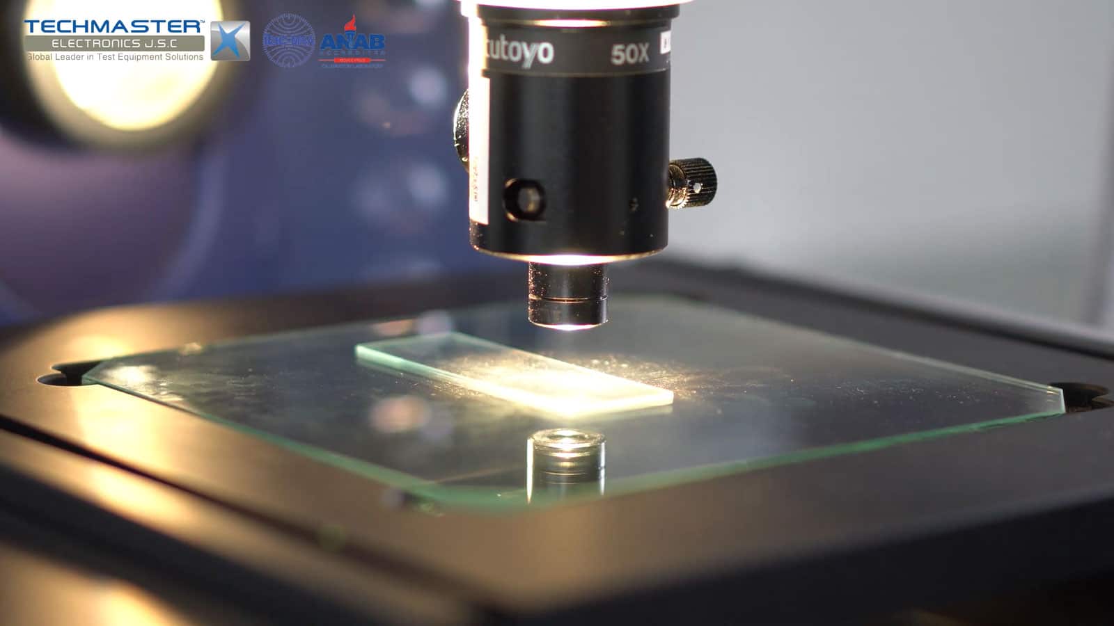
- Place standard glass scale on measuring table, alignment for crosshair of measuring machine so that one line parallel and other line is perpendicular with graduated line of standard glass.
- Perform alignment and measurement for X-axis first.
- Select the lowest size of left side of standard glass scale, for zero setting on UUT.
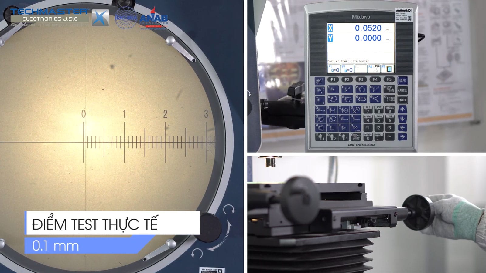
- The UUT crosshair shall be located at the middle of wide graduated line as below:
- Set zero on UUT. Using machine movement function, moving UUT crosshair for X-axis to 0.1mm distance of standard glass scale. Record value display on UUT.
- Continue measure for next distance up to max range of UUT, follow these test points:
_ 0.1, 0.2, 0.4, 0.6, 0.8, 1.0mm
_ 2, 4, 6, 8, 10mm
_ 20, 40, 60, 80, 100mm
_ 150, 200, 250, 300, 350, 400, 450 and 500mm
- Repeat all alignment and measurements steps above for Y-Axis, record values.
4.5.2. Z-axis calibration
For machine that has Z-axis measurement function, perform as below steps:
- Wringing gauge block 1mm with any gauge block size under 25mm, and face up block 1mm.
- The measuring face of base block should be appear at least 1/3 area.
- Focus UUT lens on the appearance face up of base block, to get clearly image of block surface, set zero for Z axis on UUT.
- Moving and focus UUT lens on 1mm block surface, record reading on UUT
- Repeat all steps above for blocks: 5, 10, 15, 20, and 25mm.
6. Tolerance
- Customer required tolerances are to be used for all calibrations unless otherwise noted.
- If the customer does not supply instrument tolerances then manufacturing specifications or other approved sources are to be used as the default tolerance.
- If not, tolerance in formula below will be applied:
Tolerance = (6 + 0.04L) μm
Where, L: travel amount of table, mm
- Reference documents: JIS B 7184:1999, DLVN 147:2004

