Multimeter is a familiar measuring device in the field of electricity – electronics. Multimeter will provide important measurement parameters in electrical systems, electrical equipment under test, etc. Therefore, the calibration of multimeters is extremely interested by many users. Especially, bench multimeter calibration, finding a competent and reputable calibrator is very important. Due to Bench multimeter is a high-end multimeters with high accuracy product line. This device is often used for complex test requirements. Join us to learn about the Bench Multimeter Calibration.
1. Introduction Multimeter
Multimeter is a versatile electronic – electrical measuring device. This device can take on many different measurement functions such as amperage, voltage, capacitance, frequency, capacitance, etc. Some multimeters are also equipped with a temperature measurement feature. degree. This device is also known as multi-function meter, VOM meter, DMM. Therefore, this device will provide a comprehensive view of the status of the system, electrical equipment, … Multimeter helps the maintenance, inspection and repair of electrical equipment and systems in a convenient and fast way.
2. Multimeter Classification
Multimeters are divided into 4 main types Analog Multimeter, Digital Multimeter (DMM), Pocket Multimeter, Bench Multimeter. Each type of multimeter will have different structural characteristics. However, the common factor is still the ability to measure the multimeter. Each multimeter design is ideal for certain test requirements. Let’s take a look at 4 types of multimeters.
2.1 Analog Multimeter
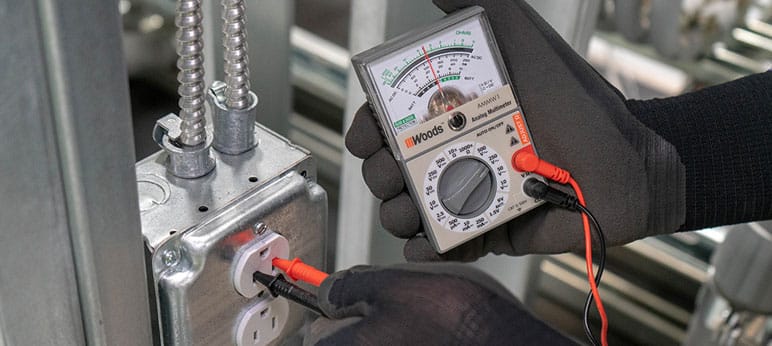
This is a basic multimeter with an extremely simple structure, displaying a needle indicator. Analog multimeter has low investment cost and measure basic parameters. The basic measurement parameters the device can measure such as ammeter, voltmeter, resistance, … However, the accuracy of this multimeter is only relative. In addition, if the needle indicator is not observed carefully, it will cause a high risk of errors. Besides, the response speed of this device is also slower than a digital multimeter. Therefore, current Analog Multimeter lines are gradually being replaced by DMM. Due to Digital Multimeter is appreciated for its convenience and accuracy.
2.2 Digital Multimeter
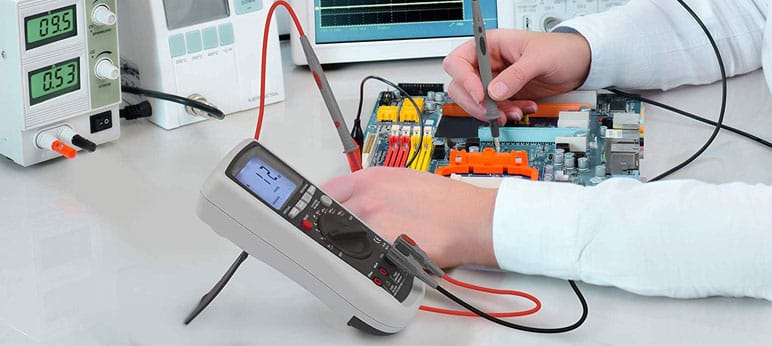
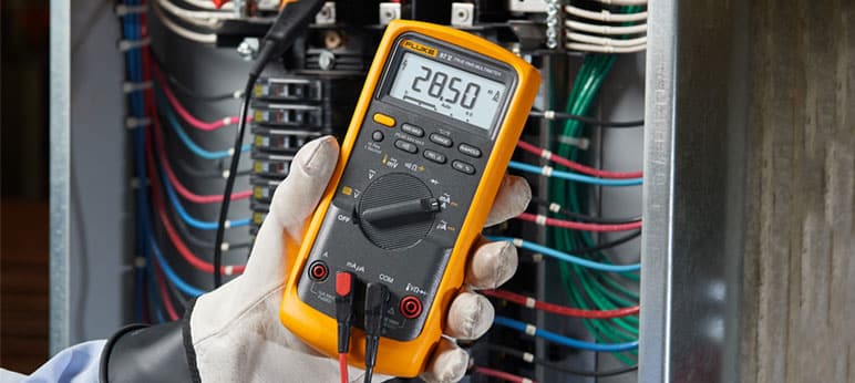
This is an extremely popular electrical measuring device with many electrical professionals, engineers, and technicians. Digital Multimeter currently has a variety of models on the market. This instrument stands out for its multi-parameter measurement capabilities and high portability. Digital Multimeter depending on demand will have a design to support measurement from basic to advanced. Besides, DMM models usually have the shockproof, waterproof,… protection features. Therefore, DMM is searched and selected by many people for equipment that supports electrical measurement.
2.3 Pocket Multimeter
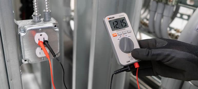
Pocket multimeters are considered an intermediate between Analog Multimeter & Digital Multimeter. This is a device that overcomes the disadvantages of Analog multimeters such as fast response speed, digital display. However, the accuracy of Pocket Multimeter is not as high as DMM. The Pocket Multimeter is often used for measurement requirements with high mobility. Compact design, can fit in a pocket is a great advantage of the device. In addition, some Pocket Multimeter models use solar power to save energy.
2.4 Bench Multimeter
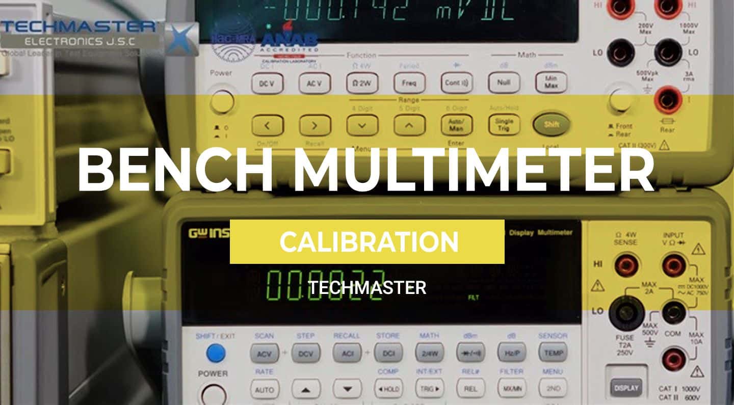
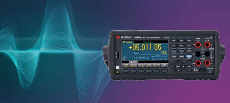
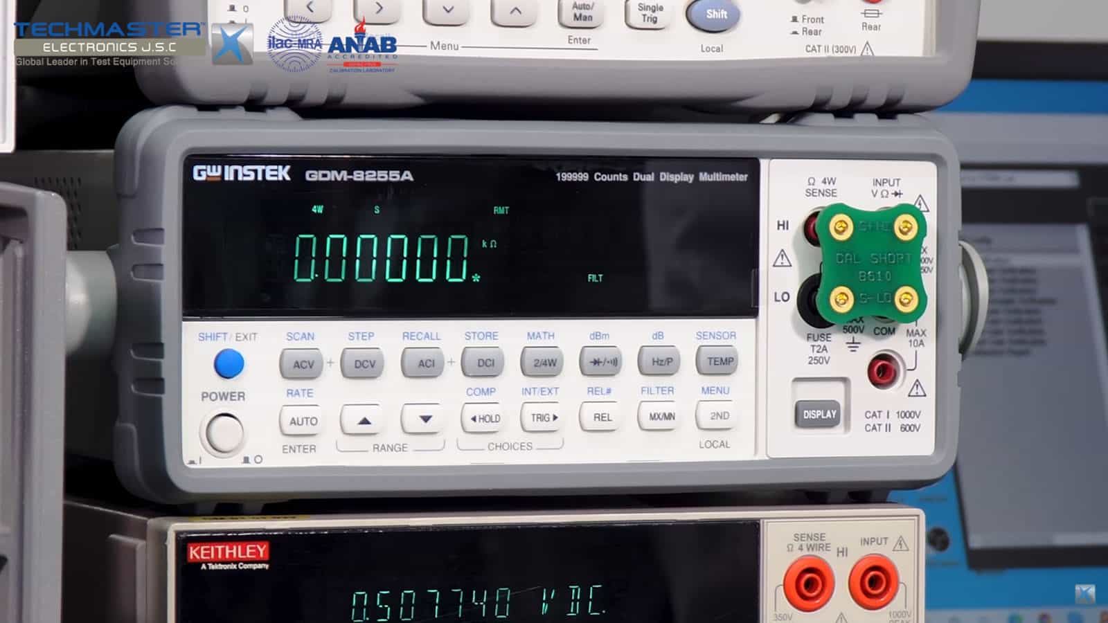
Bench Multimeter is a Multimeter with an extremely high level of accuracy. This instrument has more powerful measurement capabilities than standard multimeters. This instrument is commonly used for complex measurements in laboratories, in education, etc. The highlight of Bench Multimeter is that it offers many connectivity options such as LAN, USB or GPIB. This allows for complex automated testing and software control. Automated measurement by software greatly complements users who perform measurements with Bench Multimeter. The Bench Multimeters are capable of measuring with high accuracy readings up to 6 ½ digit.
3. Why should we calibrate Bench Multimeter?
This measuring device plays an important role in repair, inspection and quality assessment. Therefore, this device must always ensure the most stable and accurate operation. So Bench Multimeter is extremely necessary calibration. Calibration will help ensure that measurements with the Bench Multimeter always give highly reliable results. However, when you have a demand to calibrate Bench Multimeter, you need to find capable units to perform. Techmaster is a professional provider of Multimeter – Bench Multimeter calibration services. We can calibrate a wide variety of multimeters from many different brands with accuracy levels of 5 digit, 6 ½ digit, 7,8,…
4. Bench Multimeter Calibration Process
4.1 Standard and supporting device
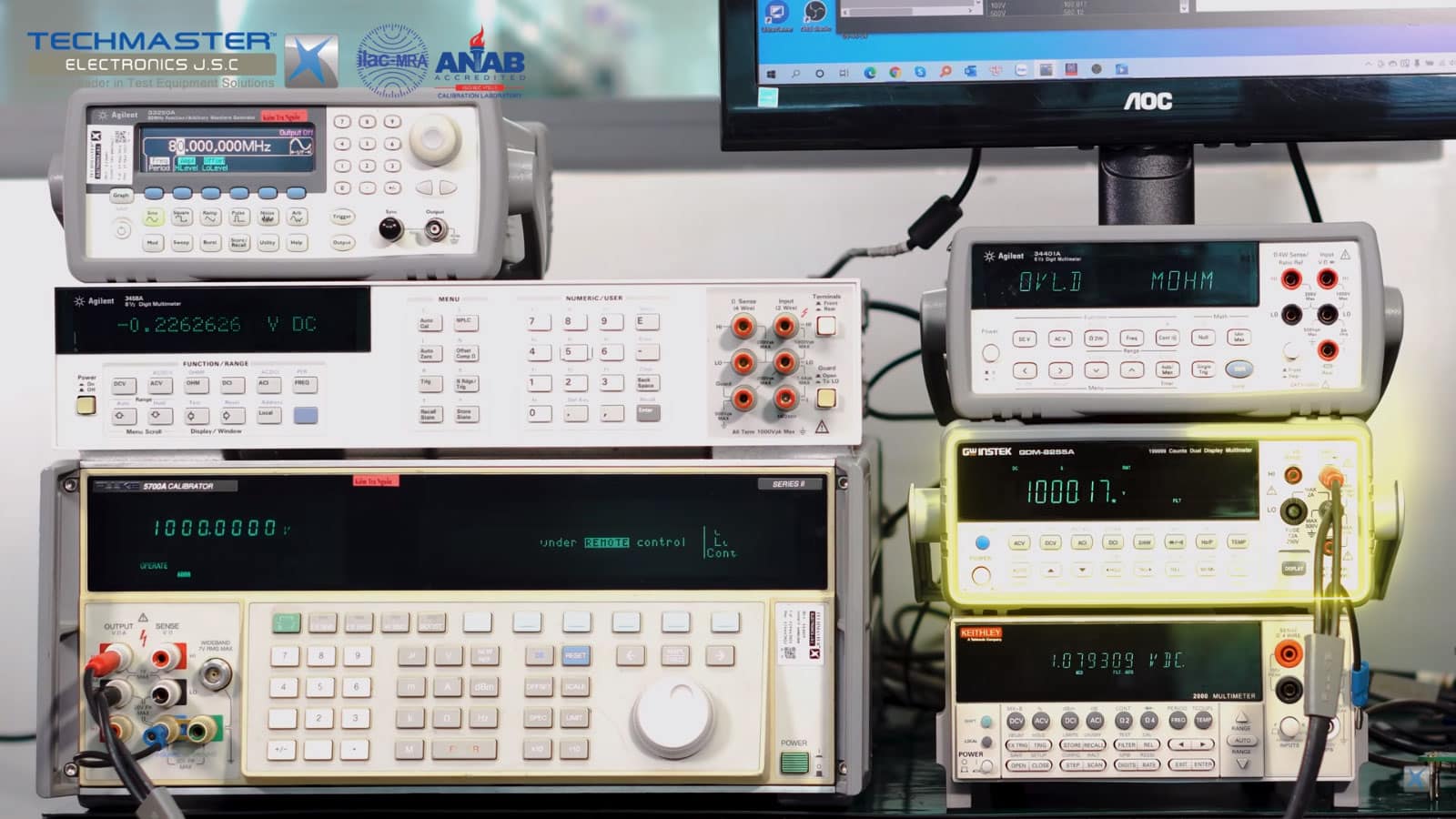
Calibrator, accuracy better than 3 times Unit Under Test (UUT).
4.2 Environment conditions
- Temperature: (18 ÷ 28)ºC
- Relative Humidity: (40 ÷ 60)%RH
4.3 Preparation
- Visually inspect the UUT for obvious damage that may affect accuracy and/or operation and note any observations.
- Technician must be familiar with calibration techniques and the operator manual of the UUT being calibrated.
- Connect TI and test equipment to appropriate power source. POWER ON and allow warm-up as required by the manufacturer.
4.4 Perform Bench Multimeter Calibration
4.4.1 DC Volts calibration
- For calibration of DC Volts function, calibration points will be perform at approximately 10%, 30%, 50%, and 95% of UUT range. Other test point from 0 to 100% UUT range can be done follow customer’s requirements.
- Connect UUT DC VOLTS terminals to Calibrator OUTPUT terminals, observing polarity.
- UUT setting switch to DC Voltage mode. Some UUT require the test leads be changed to different jacks for range changes.
- On the Calibrator set the desired output value, then press OPR/STBY switch to OPR and read UUT value when it is stable.
- Set Calibrator OPR/STBY switch to STBY.
- Repeat the above process to test each DC Voltage range of UUT.
- Disconnect UUT from Calibrator.
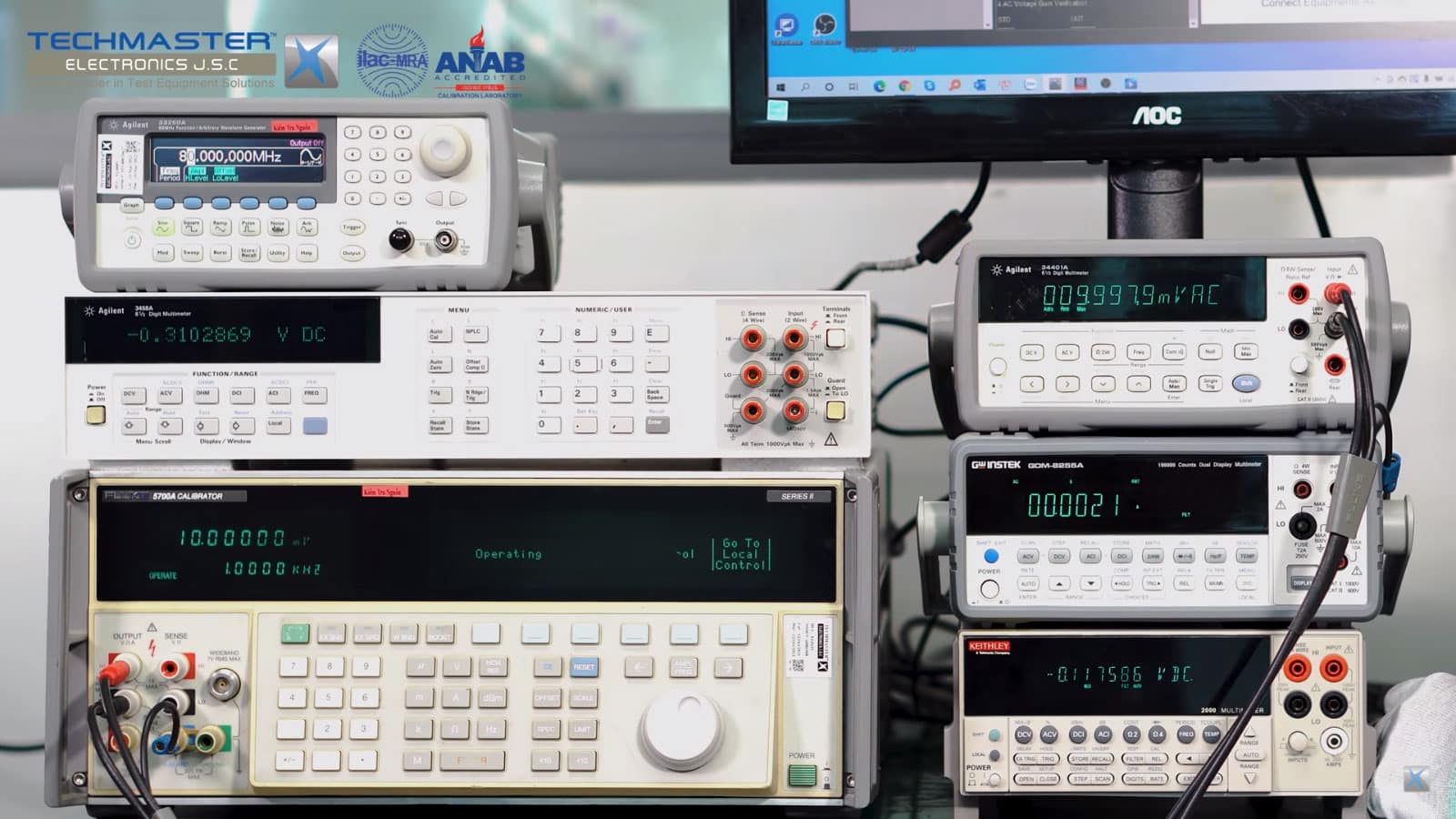
Zero offset Verification
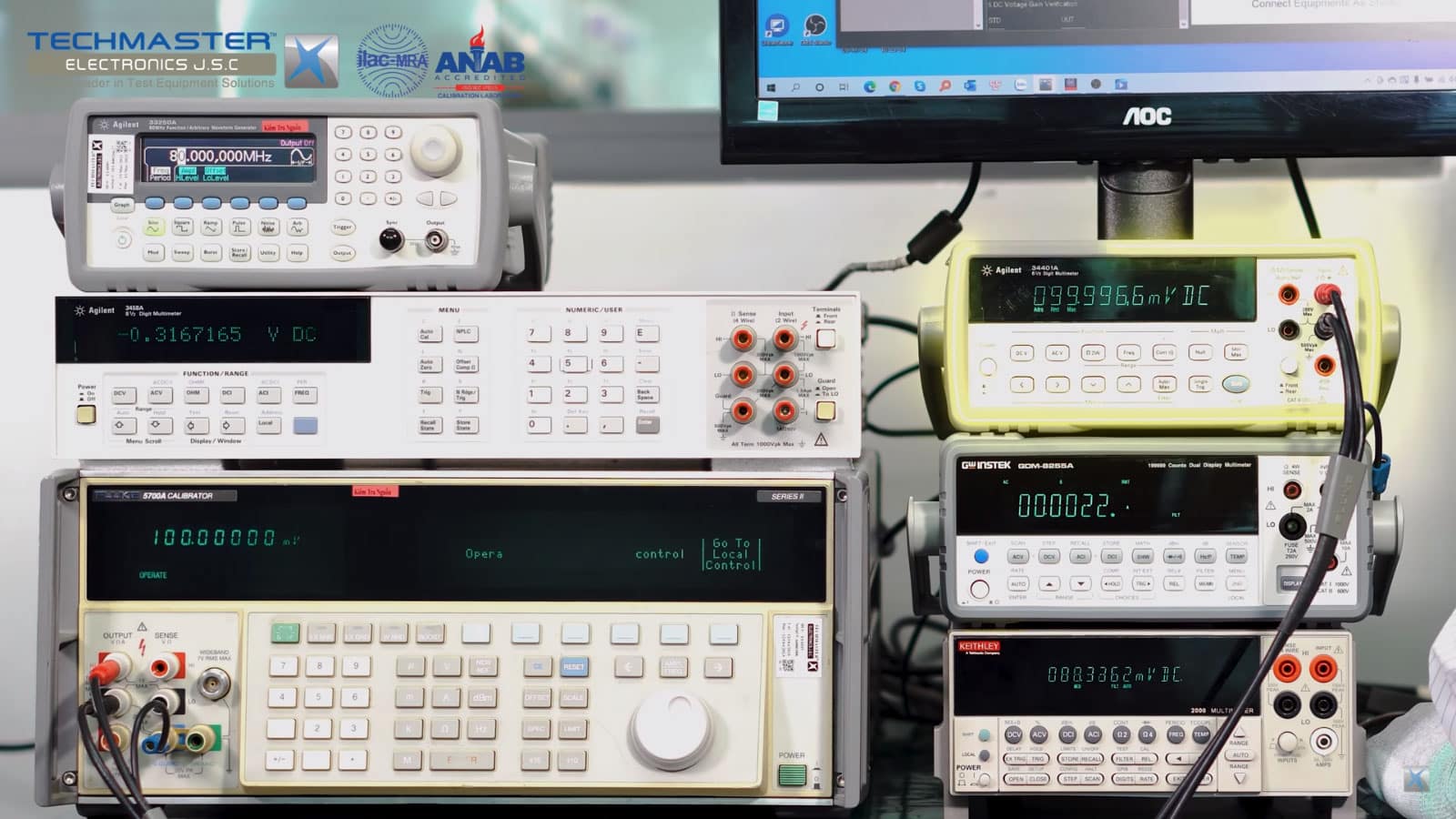
DC Voltage Gain Verification
4.4.2 DC Current Calibration
- For calibration of DC Current function, calibration points will be perform at approximately 10% and 95% of UUT range. Other test point from 0 to 100% UUT range can be done follow customer’s requirements.
- Connect UUT DC Current terminals to Calibrator OUTPUT terminals, observing polarity.
- Perform the following steps, when calibrating UUT with current values up to 20 ADC.
NOTE:
For current >3 A, must change the test lead to the 20A terminal on the Calibrator.
- UUT setting switch to DC Current mode and at range to be test. Some UUT require the test leads be changed to different jacks for range changes.
- On the Calibrator set the desired output value, then press OPR/STBY switch to OPR and read the value when it is stable.
- Set Calibrator OPR/STBY switch to STBY.
- Repeat the above process to test each DC Current range of UUT.
- Disconnect UUT from Calibrator.
AC Voltage Gain Verification
DC Voltage Gain Verification
4.4.3 AC Volts Calibration
- For calibration of AC Volts function, calibration points will be perform at approximately 10%, 30%, 50% and 95% of UUT range. Other test point from 0 to 100% UUT range can be done follow customer’s requirements.
- Connect UUT AC VOLTS terminals to Calibrator OUTPUT terminals.
- UUT setting switch to AC Voltage mode. Some UUT require the test leads be changed to different jacks for range changes.
- On the Calibrator set the desired output value at 45Hz, then press OPR/STBY switch to OPR and read UUT value when it is stable.
- Set Calibrator OPR/STBY switch to STBY.
- Repeat the above process to test each AC Voltage range of UUT at 400Hz.
- Disconnect UUT from Calibrator
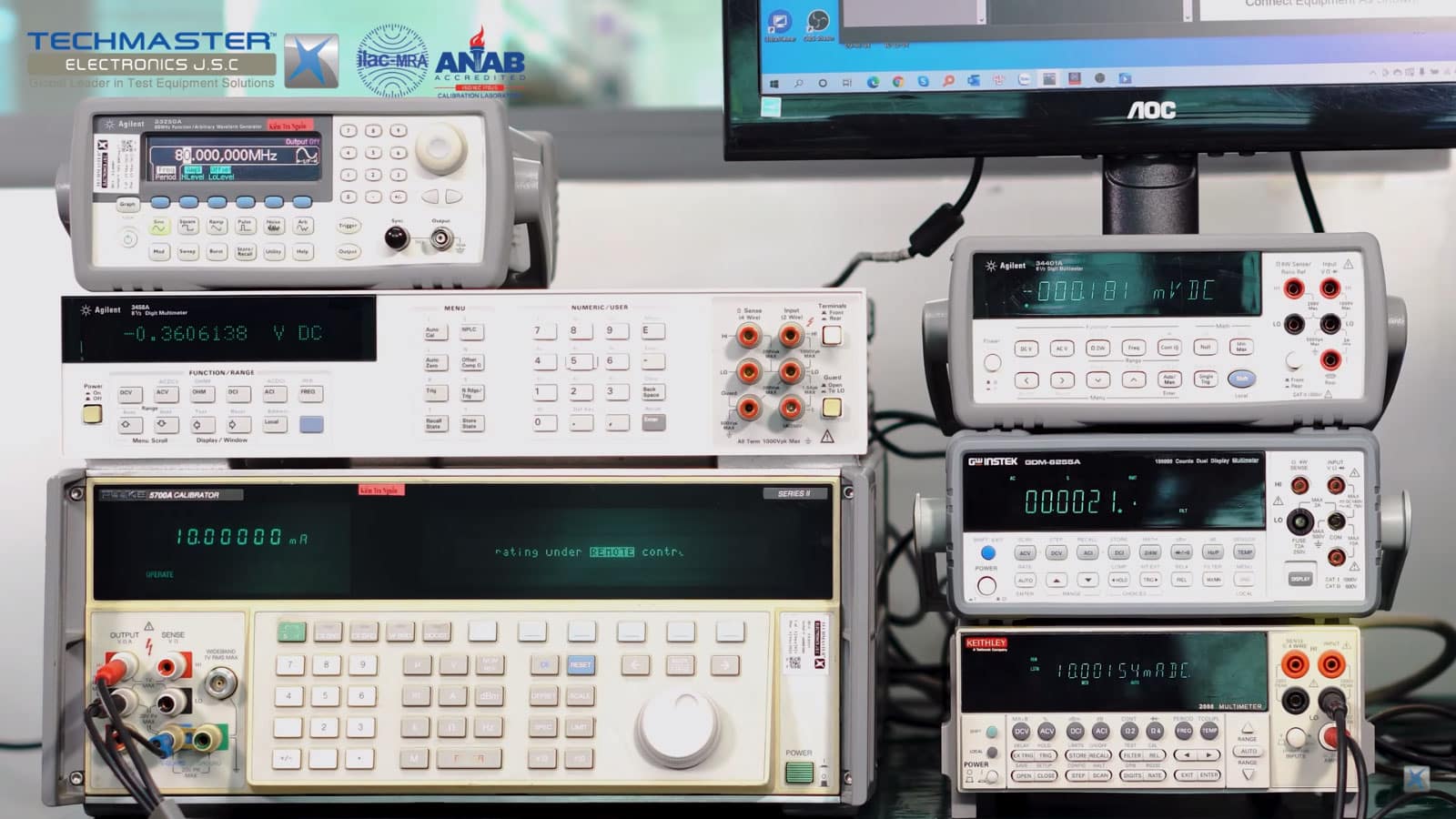
DC Current Gain Verification
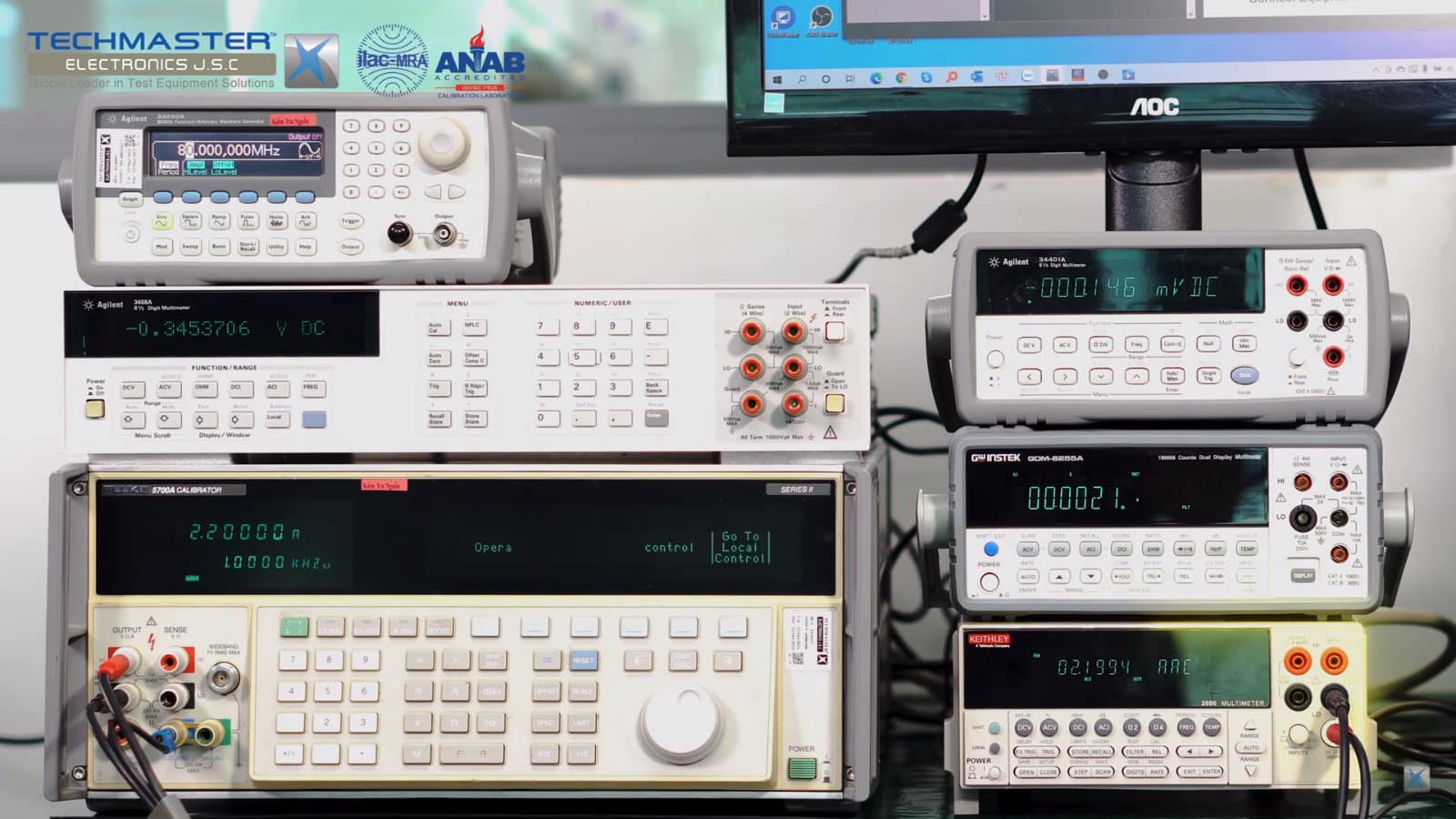
AC Current Gain Verification
4.4.4 AC Current Calibration
- For calibration of AC Current function, calibration points will be perform at approximately 10% and 95% of UUT range. Other test point from 0 to 100% UUT range can be done follow customer’s requirements.
- Perform the following steps, when calibrating UUT with current values up to 20 AAC :
- Connect UUT AC Current terminals to Calibrator OUTPUT terminals.
NOTE:
For current >3 A, must change the test lead to the 20A terminal on the Calibrator.
- UUT setting switch to AC Current mode and at range to be test. Some UUT require the test leads be changed to different jacks for range changes.
- On the Calibrator set the desired output value at 45Hz, then press OPR/STBY switch to OPR and read the value when it is stable.
- Set Calibrator OPR/STBY switch to STBY.
- Repeat the above process to test each AC Current range of UUT.
- Disconnect UUT from Calibrator.
4.4.5 Resistance Calibration
- For calibration of Resistance function, calibration points will be perform at approximately 10%, 30%, 50% and 95% of UUT range. Other test point from 0 to 100% UUT range can be done follow customer’s requirements.
- Connect UUT OHMS terminals to Calibrator OUTPUT terminals.
- UUT setting switch to Resistance mode. Some UUT require the test leads be changed to different jacks for range changes.
- On the Calibrator set the desired output value, then press OPR/STBY switch to OPR and read the value when it is stable.
- Set Calibrator OPR/STBY switch to STBY.
- Repeat the above process to test each Resistance range of UUT.
- Disconnect UUT from Calibrator.
4.4.6 Capacitance Calibration
- For calibration of Capacitance function, calibration points will be perform at approximately 90% of UUT range. Other test point from min to max UUT range can be done follow customer’s requirements.
- Connect UUT terminals to Calibrator OUTPUT terminals, observing polarity.
- UUT setting switch to Capacitance mode.
NOTE:
The output is continuously variable from 190 pF to 110 mF.
Specifications apply to both DC charge/discharge capacitance meters and AC LCR meters. The maximum allowable peak voltage is 3 V. The maximum allowable peak current is 150 mA, with an RMS limitation of 30 mA below 1.1 μF and 100 mA for 1.1 μF and above.
The maximum lead resistance for no additional error in 2-wire COMP mode is 10 Ω.
- On the Calibrator set the desired output value, then press OPR/STBY switch to OPR and read the value when it is stable.
- Set Calibrator OPR/STBY switch to STBY.
- Repeat the above process to test each Capacitance range of UUT.
- Disconnect UUT from Calibrator.
4.4.7 Frequency Calibration
- For calibration of Frequency function, calibration points will be perform at approximately min, 50% and max of UUT range. Other test point from min to max UUT range can be done follow customer’s requirements.
- Connect UUT AC VOLTS terminals to Calibrator OUTPUT terminals.
- UUT setting switch to ACV and choose Frequency Mode.
- On the Calibrator set the desired output value at 3V, then press OPR/STBY switch to OPR and read the value when it is stable.
- Set Calibrator OPR/STBY switch to STBY.
- Repeat the above process to test each point frequency of UUT.
- Disconnect UUT from Calibrator.
4.4.8 Diode Calibration
- For calibration of Diode function, calibration point will be perform at approximately 75% of UUT range.
- Connect UUT DC VOLTS terminals to Calibrator OUTPUT terminals, observing polarity.
- UUT setting switch to Diode mode.
- On the Calibrator set the desired output value, then press OPR/STBY switch to OPR and read the value when it is stable.
- Set Calibrator OPR/STBY switch to STBY.
- Disconnect UUT from Calibrator.
4.4.9 Temperature Calibration
- For calibration of Temperature function, calibration points will be perform at approximately min, 50% and max of UUT range. Other test point from min to max UUT range can be done follow customer’s requirements.
- Connect UUT DC VOLTS terminals to Calibrator OUTPUT terminals, observing polarity.
- UUT setting switch to Temperature mode.
- On the Calibrator select the thermocouple type K and enter the desired output value, then press OPR/STBY switch to OPR and read the value when it is stable.
- Set Calibrator OPR/STBY switch to STBY.
- Disconnect UUT from the Calibrator and secure all equipment
4.6. Tolerance
- Customer required tolerances are to be used for all calibrations unless otherwise noted.
- If the customer does not supply instrument tolerance then manufacturing specifications or other approved sources are to be used as the default tolerance.

