Techmaster introduce Calibration procedure for air flow meter
1. Scope of procedure
|
Unit Under Test Characteristics |
Performance Range |
Performance Method |
|
Air flow rate |
Up to 200 L/M |
Comparison to standard flow meter |
2. Standard and supporting device
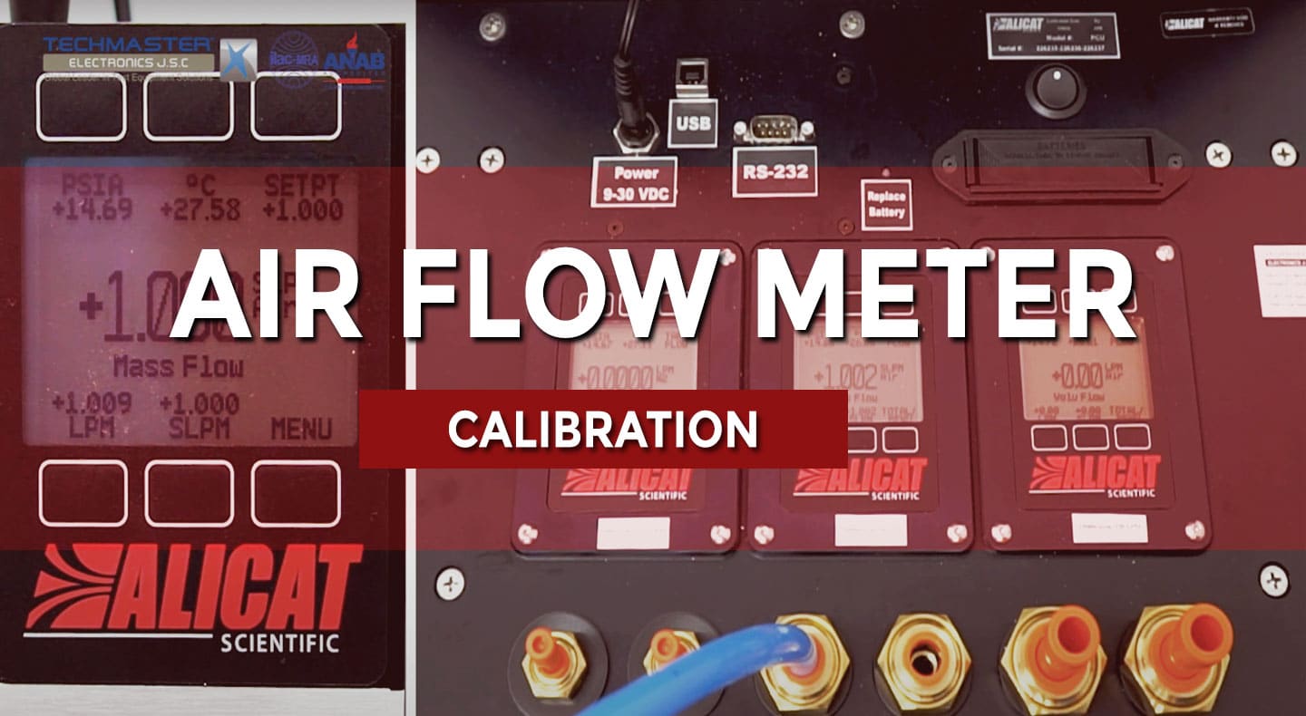
– Standard Flow Meter ALICAT PCU, flow range up to 200L/min or equivalent
– Connecting tube with various size, fitting with in/out port of Unit Under Test (UUT) and standard meter (STD).
– Air flow generator range up to 200L/min or more, with flow regulator or control valve.
– Connecting tube with various size, fitting with in/out port of Unit Under Test (UUT) and standard meter (STD).
– Air flow generator range up to 200L/min or more, with flow regulator or control valve.
3. Environment conditions
– Temperature: (20 ÷ 25)oC
– Relative Humidity: (20 ÷ 65)%RH
Note: environment conditions above apply for Techmaster inhouse laboratories. Outside this bound conditions will be considered with customer for uncertainty and measurement results.
4. Preparation
– Select suitable tubes, connect Air Flow Generator – STD meter and UUT, at the suction side or arrow direction of each equipment.
– If UUT has control / adjustable valve, then connect UUT between Generator and STD meter.
– If UUT has internal pump, then Generator shall not be used. Connect UUT to STD meter directly.
– Teflon, quick-connector can be used if need.
– Ensure that system is no leak.
– Connect Air Flow Generator, STD meter, UUT to suitable power.
– Turn all on, allow warm up at least 30minutes or follow manufacturer’s instruction.
5. Perform
– Perform test points at: 25, 50, 75 and 100% UUT range, or follow customer’s requirement.
– Press measure button on UUT and STD meter, if needed.
– Press measure button on UUT and STD meter, if needed.
– Slowly adjust flow rate output from the Generator, until STD meter reach nearly first test point.
– In case UUT has internal pump and flow setting function, then use UUT to generate test point.
– Allow for stable reading, record value of UUT and STD meter. Repeat 5 times.
– Repeat above steps for remain test points.
– Calibration now completed, set output air flow of Generator decreasing to zero.
– Turn off UUT and STD meter, take out of all components above.
6. Tolerance
– Device tolerance will be based on customer requirements, unless otherwise stated.
– If the customer has no requirements, it will be based on manufacturer specifications or other reference sources.
– If not, the tolerance ± (3% of reading +0.3%FS) will be applied.
– If the customer has no requirements, it will be based on manufacturer specifications or other reference sources.
– If not, the tolerance ± (3% of reading +0.3%FS) will be applied.

