Oscilloscope is a device capable to catch graph electronic signals to analyze and find extraordinary signals. This device possesses the characteristic ability to plot the three main shaft signal X, Y, Z. In there, X axis (time), Y axis (voltage), Z axis (brightness intensity). Oscilloscope is capable of recognizing many different signals types such as square, sawtooth, sinusoidal pulses, or even difficult signals such as video and audio. Oscilloscopes frequency range from 1Hz to several MHz. Some high-end models can display a frequency signal up to several hundred GHz.
Oscilloscopes are classified into two main types: analog oscilloscope and digital oscilloscopes.
+ Analog oscilloscope: This is an old technology oscilloscope, so the measurement frequency is quite low.
+ Digital oscilloscope: The new type has a much higher measurement frequency than analog oscilloscope. With many functions included, it brings convenience during work.
| Unit Under Test Characteristics | Performance Range | Performance method |
| DC voltage Rise Time Bandwith Time Marker | Up to 130V | Comparison to Multifunction Calibrator |
Temperature: (18 ÷ 28)°C
Relative Humidity: (40 ÷ 60)%RH
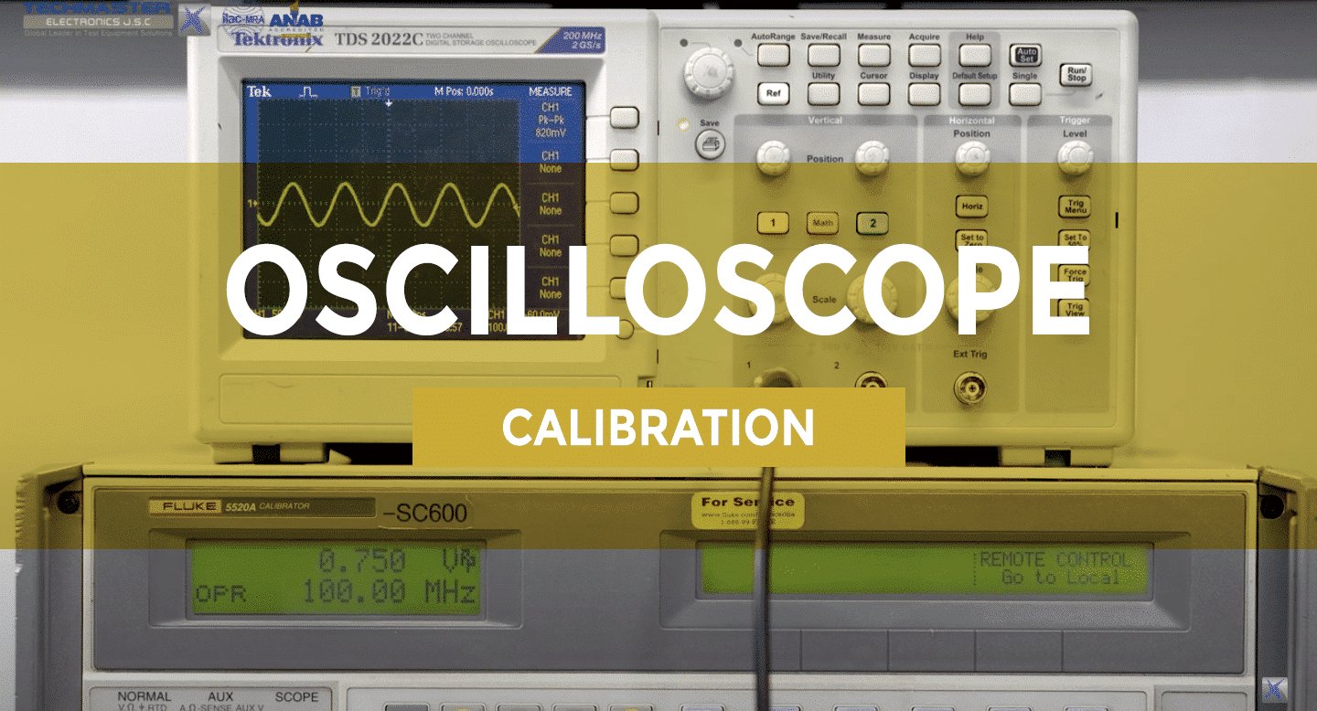
– Connect the output of STD (for example, Fluke 5520A) to the oscilloscope channel 1 input, as shown fig1, Set CH1: ON
– Setting the UUT impedance level to be tested (for devices with multiple impedance levels).
– Set the output impedance of the STD to match the impedance set on the UUT, example 50Ω.
– Configure Vertical Scale follow Impedance input point.( Depending on the manufacturer and each model) Setting STD Measurement: ON
– Measure the input Impedance of the UUT with the STD. Record this value.
– Setting STD Measurement: STBY
– Repeat above steps for remains channels of the Oscilloscope.
| 0.5mV/div | 1mV/div | 2mV/div | 5mV/div | 10mV/div | 20mV/div | 50mV/div |
| 100mV/div | 200mV/div | 500mV/div | 1V/div | 2V/div | 5V/div | 10V/div |
Note: test points in table above can be changed according to manufacturer’s manual or customer’s requirement.
– On STD: set voltage value equal 7 times value of UUT. Example, UUT setting 1mV/div, then STD setting is 7mV.
– Connect STD to CH1 of UUT as shown in Figure 2, using terminal 50 ohm
– Based on manufacturer’s manual, set to Factory Default to recall the factory default for UUT.
– Set calibration output signal to “EDGE” mode with rise time 150ps rise time (base on model UUT) and 1.2 V amplitude
– Configure the UUT:
– Press TRIGGER LEVEL to adjust the trigger level to the middle of the screen.
– Rotate HORIZONTAL POSITION and VERTICAL POSITION respectively to adjust the horizontal position and vertical position properly.
– Observe the screen of the UUT. Press Cursor -> Mode -> “Manual” to turn on the manual cursor function.
– Measure the zero point offset using manual cursor, read and record value.
– Keep the other settings of the UUT unchanged and set the vertical scale to 500 mV/div.
– Set calibrator out 3V
– Measure the zero point offset according to the method above and record the Measurement result.
– Turn off CH1. Repeat steps above for all channel respectively according to the method above and record the test results.
Calibration now completed, turn off, disconnect and secure all equipment.
Note : Other model of equipment reference to the manufacturer’s instructions or customer’s requirement.
– Procedure: 33k3-42950-1
– Service Guide Keysight DSOX1204A/G
New Techmaster Headquarters: Strategic Vision at a Prime Location In the dynamic context of Vietnam’s…
Techmaster and Keysight Technologies Announce strategic partnership in Vietnam Techmaster is proud to announce its…
When working in toxic or low-oxygen environments, safety begins with proper respiratory protection. The 3M…
Vertical accuracy is a key factor that determines the measurement quality of an oscilloscope. It…
In the latest update of the Scope of Accreditation to ISO/IEC 17025:2017 and ANSI/NCSL Z540-1-1994…
ISO 17025 certification ensures that laboratories meet international standards for testing and calibration competence. It…