Why Is Oscilloscope Vertical Accuracy Important
The precision of voltage measurements in an oscilloscope is affected by several factors:
The Analog-to-Digital Converter (ADC) is responsible for converting analog voltage signals into digital form. The higher the number of ADC bits, the more voltage levels the oscilloscope can detect, resulting in higher resolution and more accurate voltage measurements.
Ví dụ: An HD3 Series oscilloscope with a 14-bit ADC offers 64 times higher resolution than an 8-bit oscilloscope.
All oscilloscopes produce some level of internal noise. The noise floor represents the minimum detectable noise level of an oscilloscope. A lower noise floor allows the oscilloscope to measure smaller signals more accurately.
The frequency response describes an oscilloscope’s ability to accurately process signals at different frequencies. To ensure precise voltage measurements, the oscilloscope must have a flat frequency response, meaning it amplifies all frequencies within its bandwidth evenly. If the frequency response is not flat, some frequencies may be amplified more than others, leading to inaccurate measurements.
Proper calibration ensures that the oscilloscope provides accurate voltage measurements.
Phase delay refers to the phase shift that occurs as a signal passes through the oscilloscope. Phase delay can distort the waveform and lead to inaccurate voltage measurements.
When the oscilloscope is set to a very small vertical sensitivity, it may switch to software magnification mode. In this mode, the oscilloscope enlarges the displayed signal without increasing the actual resolution, reducing measurement accuracy.
Probes are used to connect the oscilloscope to the circuit being tested. Each probe has its own frequency response and impedance, which can affect voltage measurement accuracy.
The formula for achieving the highest vertical accuracy in an oscilloscope is:
Highest ADC Bit Count + Lowest Noise Floor = Highest Vertical Accuracy
Explanation:
In conclusion, to achieve the highest vertical accuracy, both factors must be optimized: maximize the ADC bit and minimize the noise floor.
Higher ADC resolution improves measurement accuracy by increasing the oscilloscope’s vertical resolution. Vertical resolution refers to the smallest quantization level defined by the ADC in the oscilloscope. In other words, it is the smallest voltage level the oscilloscope can detect and display.
Example: An oscilloscope with an 8-bit ADC can encode the analog input into one of 256 levels. This means the oscilloscope can only display voltage in multiples of 1/256 of the full vertical scale. In contrast, an oscilloscope with a 14-bit ADC can encode the analog input into one of 16,384 levels. This allows the oscilloscope to display voltage in multiples of 1/16,384 of the full vertical scale, ensuring finer resolution and more precise measurements.
Vertical resolution is not the only factor affecting measurement accuracy. Other factors, such as oscilloscope front-end noise, can also have an impact. However, higher ADC resolution remains a critical factor for achieving high measurement accuracy.
The number of bits in the Analog-to-Digital Converter (ADC) directly affects an oscilloscope’s vertical accuracy. A higher ADC bit count results in greater vertical accuracy because the bit count determines the vertical resolution of the oscilloscope, which refers to the smallest voltage level the oscilloscope can detect.
Key points explaining the impact of ADC bits on vertical accuracy:
An ADC with more bits can distinguish a greater number of voltage levels. This leads to better resolution and the ability to display smaller voltage changes more accurately.
ADCs work by quantizing the input analog signal into discrete steps. The number of ADC bits determines the number of quantization steps available. A higher bit count results in smaller quantization steps, enabling more precise measurements.
Example: An 8-bit ADC oscilloscope can encode an analog input into 256 levels, while a 14-bit ADC oscilloscope can encode it into 16,384 levels. This means a 14-bit ADC oscilloscope can detect voltage levels 64 times smaller than an 8-bit ADC oscilloscope.
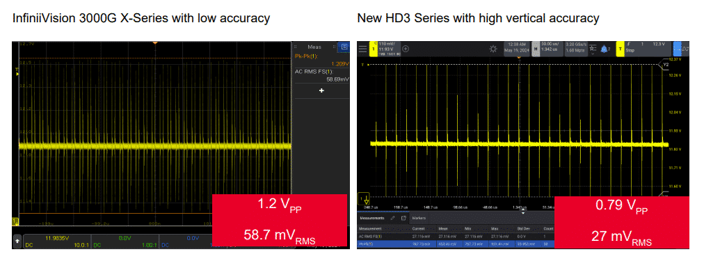
When comparing measurements between the Keysight InfiniiVision 3000G X-Series and the HD3 Series, the HD3 Series provides significantly more accurate measurements. This is because the HD3 Series has a 14-bit ADC with a low noise floor of 50 µV RMS, whereas the 3000G X-Series only has an 8-bit ADC with a noise floor of 250 µV RMS. This difference greatly impacts measurement accuracy.
If the noise level exceeds the ADC quantization level, increasing the ADC bit count will not improve accuracy. Therefore, to fully utilize a high-bit ADC, the oscilloscope must also have a low noise floor.
The resolution of an Analog-to-Digital Converter (ADC) is a crucial factor in determining an oscilloscope’s vertical accuracy. It refers to the smallest quantization level the ADC can distinguish, representing the smallest voltage change the oscilloscope can detect and display.
This means a 14-bit ADC has 64 times higher resolution than an 8-bit ADC (16,384 / 256 = 64).
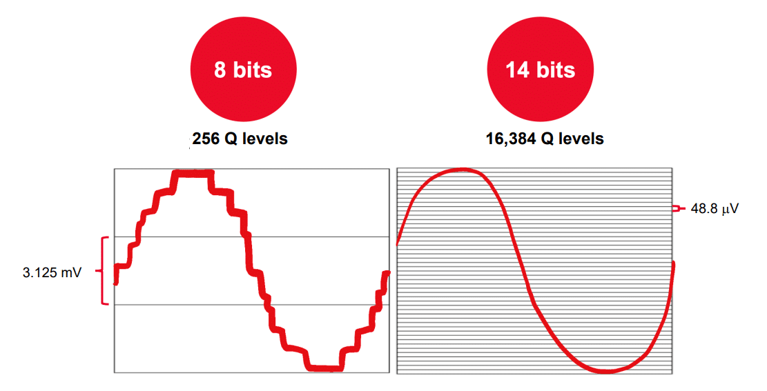
Suppose two oscilloscopes are set to a full vertical scale of 800 mV:
This means a 14-bit oscilloscope can detect and display voltage changes as small as 48.8 µV, while an 8-bit oscilloscope can only detect changes larger than 3.125 mV.
The higher resolution of a 14-bit ADC provides greater vertical accuracy, allowing the oscilloscope to display finer details and more precise measurements. This is especially critical when measuring small signals or subtle voltage changes within larger signals.
High-resolution modes enhance oscilloscope accuracy by increasing the effective bit depth. Essentially, they provide more quantization levels to represent the analog signal. While a higher theoretical ADC bit count increases resolution, the improvement also depends on the oscilloscope’s front-end noise.
Example: The InfiniiVision HD3 Series oscilloscope uses advanced techniques to increase its resolution from a native 14-bit ADC to an effective 16-bit resolution.
This technique works by sampling the signal at a much higher rate than what is typically required. The oversampling generates more data points, allowing for more detailed signal processing. The signal is then processed using digital algorithms to remove noise and improve accuracy.
As a result, the combination of high sampling rates and digital processing enables the oscilloscope to capture smaller signals and display them more clearly without requiring any hardware modifications.
While a higher ADC resolution can offer an excellent ENOB (Effective Number of Bits), poor front-end noise performance in the oscilloscope can significantly reduce the system’s overall ENOB. As a result, users will not be able to fully utilize the additional ADC bits.
Noise can originate from various sources, including:
ENOB (Effective Number of Bits) is a measure used to evaluate the real-world performance of an oscilloscope. It not only reflects the resolution of the ADC but also takes into account factors such as noise and signal distortion. However, the overall ENOB of an oscilloscope is typically lower than the ENOB of the ADC because it is affected by other components in the system, such as input circuits and other signal path elements.
Although a higher ENOB generally means more accurate measurements, engineers should not rely solely on ENOB to evaluate signal integrity. This is because ENOB does not account for factors like offset errors or phase distortion, both of which can contribute to measurement inaccuracies.
The noise floor of an oscilloscope plays a critical role in determining vertical accuracy. It refers to the minimum noise voltage level that the oscilloscope can detect. Any signal smaller than the noise floor will be masked by noise and cannot be measured accurately. Therefore, the lower the noise floor, the higher the oscilloscope’s vertical accuracy.
Quantization noise is an unavoidable form of noise that occurs during the conversion of an analog signal to a digital signal by the ADC in an oscilloscope.
An analog signal is continuous and smoothly varies over time (like a sine wave). The ADC converts this continuous signal into a digital signal by dividing the voltage scale into discrete levels, known as quantization levels. The ADC samples the analog signal at specific time points. Each sample is assigned the nearest corresponding quantization level. For example, if the analog signal has a value of 1.23 V but the nearest quantization level is 1.2 V, the ADC will choose 1.2 V. The difference between the actual value of the analog signal (1.23 V) and the assigned value (1.2 V) is called quantization error.
This quantization error manifests as quantization noise, which overlaps the digitized signal. The level of quantization noise is inversely proportional to the resolution of the ADC. An ADC with more bits can represent the signal with more quantization levels, resulting in smaller quantization errors and lower quantization noise.
Although quantization noise is present in all oscilloscopes, it is usually not the primary source of noise. However, quantization noise can become significant when measuring very small signals, where maintaining a low overall noise level is crucial.
To measure the noise level of an oscilloscope, disconnect the inputs to ensure that no external signals interfere with the results. Then, set the input to 50 Ω or 1 MΩ. At the same time, set the sample rate to a high value with a large memory (1 Mpt) to cover the oscilloscope’s full bandwidth. Operate the oscilloscope with infinite persistence and observe the thickness of the waveform displayed. The thicker the waveform, the higher the internal noise generated by the oscilloscope.
Additionally, use the “AC RMS” measurement function to determine the specific noise level at each vertical (V/div) setting. Each channel of the oscilloscope will have a different noise level. The measurement results provide a better understanding of the oscilloscope’s ability to measure signals smaller than the noise. Since noise affects both the time and voltage in measurements, an oscilloscope with low noise will provide more accurate results.
Minimizing noise is crucial for oscilloscope measurements because noise represents the vertical deviation from the actual signal value. Users will not be able to see details of signals smaller than the oscilloscope’s noise level.
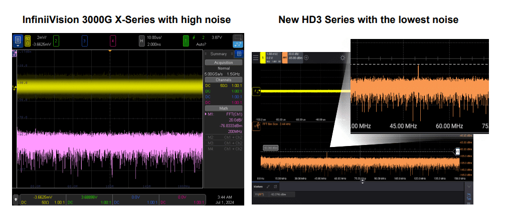
Example: When measuring a 53 µV signal on a Keysight InfiniiVision 3000G X-Series oscilloscope with a background noise level of 372 µVRMS, the signal cannot be seen on the Fast Fourier Transform (FFT). This is due to the high background noise level. However, when using the Keysight InfiniiVision HD3 series oscilloscope with a lower background noise level of less than 50 µVRMS, the 53 µV signal can be clearly seen on the FFT.
Additionally, if the noise level is higher than the ADC quantization level, users will not be able to take advantage of the extra ADC bits. Noise can come from various sources, but the oscilloscope’s front end is the most important factor affecting its overall noise.
The effective number of bits (ENOB) is a measure of an oscilloscope’s dynamic performance, taking noise into account. It indicates how many bits of the Analog-to-Digital Converter (ADC) are effectively useful for making measurements, considering the presence of noise. The ENOB value is always lower than the ADC’s theoretical bit count.
Example: An InfiniiVision 3000G/4000G X-Series oscilloscope with an 8-bit ADC has a system ENOB of approximately 6.9 bits. In contrast, an HD3 Series oscilloscope with a 14-bit ADC achieves a system ENOB of over 10.4 bits.
ENOB is not a fixed value but is represented as a series of curves. These curves are generated by sweeping a sine wave with a fixed amplitude across different frequencies, while the oscilloscope measures results at specific vertical scale settings.
In summary, ENOB provides users with a realistic evaluation of an oscilloscope’s accuracy under noisy conditions. It helps in selecting the right equipment for applications requiring precise measurements.
ENOB (Effective Number of Bits) and ADC bit resolution are two distinct concepts, but both are related to an oscilloscope’s vertical performance.
Producers may provide the ENOB value of the ADC itself, but this value is often not very meaningful. The oscilloscope’s front-end noise can significantly reduce the overall system ENOB, making it a more practical measure of real-world performance.
In summary, ADC resolution is an ideal specification based on the ADC’s theoretical capability. In contrast, ENOB is a realistic measurement of the oscilloscope’s performance, taking noise and other imperfections into account.
ENOB (Effective Number of Bits) is a dynamic performance measure that indicates how many ADC bits are effectively useful for performing accurate measurements. An oscilloscope’s ENOB can be reduced by several factors:
In summary, to achieve a higher ENOB and more accurate measurements, it is crucial to minimize noise levels in the oscilloscope system. Selecting an oscilloscope with low front-end noise and considering factors like offset errors and phase distortion are essential for maintaining accurate measurement results.
Why should engineers not rely solely on ENOB for signal integrity evaluations?
ENOB (Effective Number of Bits) is an important specification for assessing an oscilloscope’s measurement quality. However, engineers should not rely solely on ENOB when evaluating signal integrity for the following reasons:
To comprehensively evaluate signal integrity, engineers should consider additional factors:
A flat frequency response ensures the oscilloscope evenly processes all frequencies within its bandwidth, resulting in accurate waveform acquisition and display.
Low noise levels are critical for observing small signals or subtle changes in larger signals. High noise levels can obscure important signal details and reduce measurement accuracy.
An accurate timebase is necessary for precise measurement of signal timing characteristics, such as pulse width, rise time, and propagation delay.
Jitter refers to deviations from the ideal horizontal position of the signal. Excessive jitter can impact the accuracy of timing measurements.
Đáp ứng tần số phẳng là rất quan trọng đối với máy hiện sóng. Chúng đảm bảo rằng máy hiện sóng có thể thu và hiển thị dạng sóng một cách chính xác. Đáp ứng tần số phẳng có nghĩa là máy hiện sóng xử lý tất cả các tần số trong băng thông của chúng một cách đồng đều, mà không khuếch đại hay suy giảm bất kỳ tần số nào.
A flat frequency response is crucial for oscilloscopes as it ensures accurate waveform acquisition and display. A flat frequency response means that the oscilloscope processes all frequencies within its bandwidth evenly, without amplifying or attenuating any particular frequency.
Key reasons why a flat frequency response is important for oscilloscopes:
If the frequency response is not flat, some frequencies will be amplified or attenuated more than others. This results in inaccurate amplitude measurements, especially when analyzing signals with multiple frequency components, such as square wave signals.
A non-flat frequency response can distort waveforms, making it difficult to analyze and interpret signal behavior. Sharp edges in waveforms might appear rounded or distorted, leading to misinterpretation.
Fast edges in signals contain multiple harmonic frequencies. An oscilloscope must accurately measure the amplitude of each harmonic component. A flat frequency response ensures that all harmonics are measured accurately, providing detailed information about the signal’s frequency content.
A flat frequency response also ensures a consistent phase response, meaning all frequencies pass through the oscilloscope with the same phase delay. This is crucial for preserving the signal’s time integrity and preventing waveform distortion caused by phase shifts.
Filters used in oscilloscopes to ensure accurate measurements.
When an oscilloscope combines both analog and correction filters, the signal is processed with higher precision. A flat frequency and phase response allow the oscilloscope to faithfully measure and display signals without distortion or inaccuracies.
Example: High-quality oscilloscopes, such as the HD3 Series, utilize both analog and correction filters, ensuring a uniform and flat frequency response for accurate and reliable signal measurements.
Correction filters play a crucial role in improving signal accuracy in oscilloscopes. They ensure that all frequency components of a signal are processed uniformly, resulting in more accurate and reliable waveforms for analysis.
How correction filters improve signal accuracy:
Oscilloscopes use analog filters to eliminate noise and unwanted signals. However, analog filters can introduce amplitude and phase distortion, especially at higher frequencies. Correction filters are specifically designed to counteract these imperfections by applying inverse characteristics. This results in a flatter overall frequency response.
Correction filters are implemented through hardware DSP (Digital Signal Processing) blocks. These filters are carefully tuned for specific oscilloscope models to produce a flat amplitude and phase response. This means the oscilloscope processes all frequencies within its bandwidth evenly, without amplifying or attenuating any specific frequency. Additionally, all frequencies experience the same phase delay, maintaining signal integrity.
By compensating for amplitude and phase distortion, correction filters enable the oscilloscope to capture waveforms more accurately. This is essential for precise measurements, harmonic analysis, and reliable signal interpretation.
Vertical scaling in an oscilloscope plays a crucial role in determining how effectively the ADC bits are utilized for signal measurement. Proper adjustment of vertical scaling can help optimize the oscilloscope’s resolution.
Impact of vertical scaling on ADC bit utilization:
When the waveform is scaled to fill most of the vertical display, the oscilloscope’s ADC is fully activated. This means all available ADC bits are being used, resulting in maximum resolution for the measurement.
Example: On an oscilloscope with a 14-bit ADC, if the waveform occupies the entire screen, all 14 bits are used to represent the signal.
If the waveform occupies only a small portion of the vertical display, the number of ADC bits effectively utilized decreases. This leads to a loss of resolution and reduced measurement accuracy.
Example: If the waveform occupies half the screen, only 12 ADC bits are effectively used. If it occupies only a quarter of the screen, the number of effective ADC bits drops to 10 bits.
When the oscilloscope hardware cannot further reduce the vertical scale, it switches to “software magnification” mode. In this mode, the signal is magnified visually on the screen but without adding real resolution or increasing the number of ADC bits used.
To achieve the highest resolution, users should adjust the vertical scaling so that the waveform occupies most of the vertical display, ensuring the full ADC bit depth is utilized for accurate and detailed measurements.
Software magnification, unlike hardware scaling, does not increase the resolution of measurements. While the signal may appear larger on the screen, no additional information is captured, and the measurement accuracy remains limited by the ADC’s original resolution.
Here are the limitations of software magnification compared to hardware scaling:
Software magnification simply enlarges the displayed signal without adding any extra data points. As a result, it does not improve measurement resolution. In contrast, hardware scaling fully utilizes the ADC’s range, leading to higher resolution measurements.
Software magnification does not provide actual improvements in resolution; it only zooms in on the displayed signal. This reduces accuracy when measuring small signals or detecting subtle changes in larger signals because the oscilloscope does not use additional ADC bits to enhance detail. On the other hand, hardware scaling maximizes the use of ADC bits, resulting in more accurate measurements.
Software magnification can be misleading. Users may believe they are observing more signal detail than is actually present. This false assumption can lead to incorrect conclusions during signal analysis. It’s essential to recognize that software magnification cannot replace proper hardware scaling for accurate results.
Adjusting vertical scaling on an oscilloscope plays a crucial role in optimizing measurement resolution. The goal is to utilize as many bits of the Analog-to-Digital Converter (ADC) as possible while keeping the waveform clearly displayed on the screen.
To optimize resolution through vertical scaling:
New Techmaster Headquarters: Strategic Vision at a Prime Location In the dynamic context of Vietnam’s…
Techmaster and Keysight Technologies Announce strategic partnership in Vietnam Techmaster is proud to announce its…
When working in toxic or low-oxygen environments, safety begins with proper respiratory protection. The 3M…
In the latest update of the Scope of Accreditation to ISO/IEC 17025:2017 and ANSI/NCSL Z540-1-1994…
ISO 17025 certification ensures that laboratories meet international standards for testing and calibration competence. It…
In the manufacturing and mechanical fields, a welder isn't just a tool. It stands as…